The day AEM Performance Electronics saved my engine was a perfect Friday in June at Mosport, also known as… Mosport. Sorry Canadian Tire, it’s Mosport and you know it’s Mosport. It’s my favourite place on the planet. There’s nothing like spending a day exhausting your body, mind and car and then heading to the banquet center for a few beers. This is probably as close to heaven as I’m likely to get.

I’ve been to many of the revered racetracks including Laguna Seca, Watkins Glen and the Nurburgring and nothing compares to Mosport. It’s impossible to explain without driving it, no video will ever come close, mainly because you can’t feel or even see the rollercoaster drops of elevation while cresting a hill and turning at 100+ MPH in 2D on video or in a video game. All racetracks are awesome and most have something really cool about them, but there is nothing like Mosport for me, maybe because there is no such thing as a perfect lap at this place. You can find a pile of time just by shifting your line half a foot one way or another or just manning up a bit harder. It’s both technical and exhilarating/terrifying.
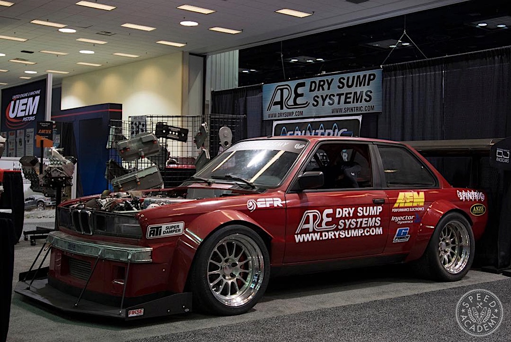
But first let’s rewind back to when the car made its debut on the PRI Show floor. Unlike many show cars, there was nothing imaginary on it, no Bluetooth driveshafts or telekinetic turbos. The car was done.
But much to the dismay of the guys helping me get the car on and off the show floor, the car wasn’t drivable yet because I wanted to check everything over before trying to start it. As the Canadian weather became friendlier to organic life and Ethanol powered cars, it seemed ready to fire. The complete rewiring of the car I did, covered in the previous chapters, with the AEM Infinity and ECUMaster PMU16, seemed to all be correct. First I made sure there were no short circuits, and everything that was supposed to get +12 did, everything that was supposed to be grounded was, and I turned on the controllers.

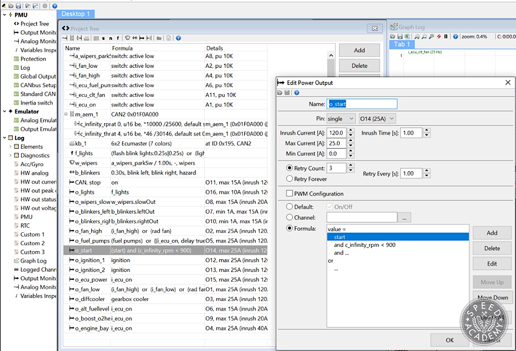
Setting up the PMU16 was quick and easy, and let me do things with button clicks that would otherwise require some really funky button, relay and wire arrangements. I defined some of the AEMnet CANBUS messages from the Infinity and I could do things like have the starter button only fire up the starter output if the engine wasn’t already running. The fuel pumps could be turned on by the keypad to prime the system and then turn the button off because they’ll keep running with the engine running and the Infinity saying to turn on the pumps – something my car didn’t have before, leaving a dangerous possibility of the pumps continuing to run in the event of a crash. Or the cooling fans could be turned on by the rad switch, the ECU or by the button on the dash. It comes with built-in modules for blinkers and wipers. This is on top of things like the fuses being virtual so if you short something out, the “fuse” can retry if you set it to, or you can log what’s happening to see how much current was being drawn. I had this problem with the fans, having to add a 2nd 25A output to the circuit because in the dead of winter it took so much current to fire up the fans that it was tripping the over-current threshold. But rather than getting out circuit testing tools, you turn on the logger and see exactly what’s happening.
I checked that no leaks had developed, all fluids were being delivered where they needed to go and the Infinity was happy with what it was getting from the engine, verifying the timing. Everything seemed good and I tried to fire it up. I tried to crank it and nothing much was happening but then there was a big blast out of the exhaust. I always say that when you have engine trouble, ignore all the fanciness your car may have. Start with what it takes for the engine to run which hasn’t changed for over 100 years – air and fuel being compressed and ignited at the right time. My spark plugs were firing, they smelled of fuel (which I could also smell and even hear out of the exhaust), the timing was right, there seemed to be no reason left except the last one. I had used the example E36 M3 configuration provided with the Infinity as a starting point for things like the timing and it made sense, and I verified it with the timing light. But the timing light can only tell you that the engine is at the point relative to Cylinder 1 TDC that you think it should be and a four stroke engine visits that point twice during a complete cycle – once for compression and once for exhaust. I videoed my timing ring with my phone at high frame rate and replayed it to see how far after the last flash the engine stopped. It should have been just past the exhaust stroke TDC (it rotated a full turn after the last flash), so the Cylinder 1 cam lobes should be just past being pointed away from each other. I pulled the valve cover and…
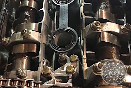
The cams were just past the compression TDC. So the timing was 360 degrees off and the engine was trying to fire on the exhaust stroke, which is why the fuel that was piled up during the impotent compression strokes was being flame-thrown out of the exhaust. I moved the timing by 60 teeth (the trigger wheel has 58 teeth with a 2 tooth gap, aka 60-2) and the engine fired up faster than it ever had before and ran perfectly! The Infinity syncs almost instantly.

The car was ready to dyno!
But Wait, There’s More…
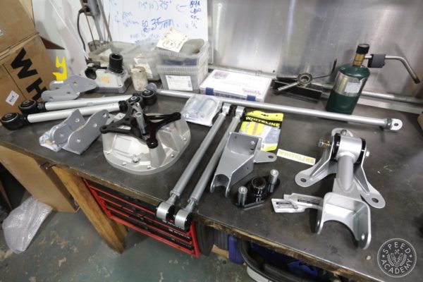
Some of you may have noticed in the last photo, there is some stuff going on that suggests that I just skipped a lot of things that happened. The reality is that this car has always been my expression for learning how to turn my automotive imagination into reality and while all I planned to do over winter was build a flat floor and diffuser, I ended up doing everything but that.
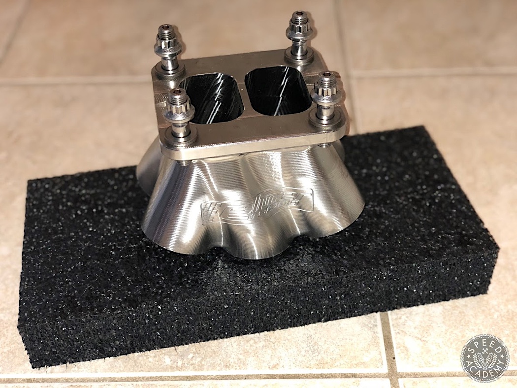
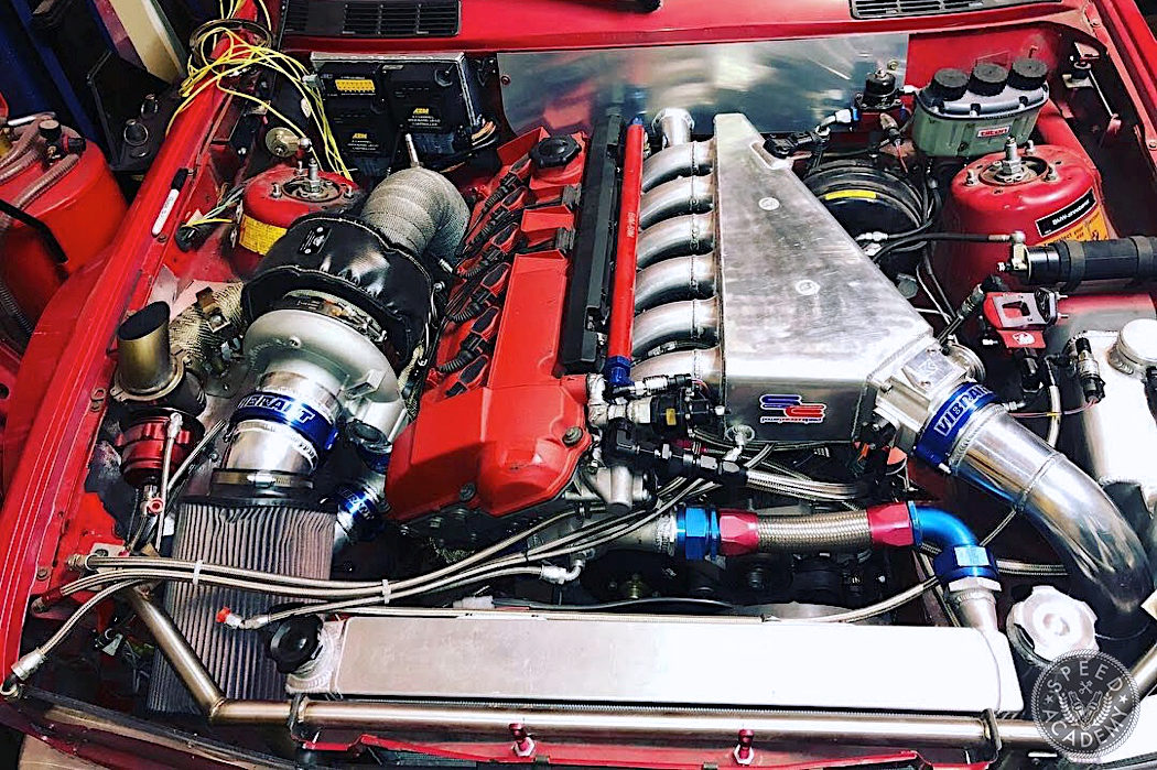
First, at PRI, Elmer Racing, who build the Thor engine for the wild WTAC RP968, had something that interested me a lot more than a $250,000 Porsche 4 banger. I had always used an open collector manifold because of the narrow engine bay and the way the cylinders are paired up in an inline-6, there was no room to do a traditional twinscroll manifold. But Elmer were showing CNC billet stainless collectors, including this “rotated” design which paired up 3 cylinders per scroll but arranged them in a way that would fit the same as an open collector. I got home and I couldn’t let it go and ordered one.
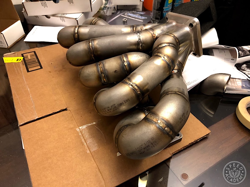
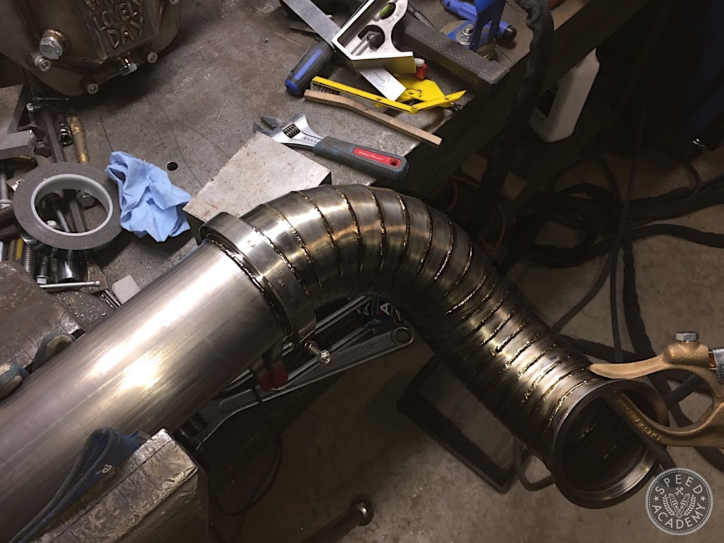
My turbo manifold was the last thing on my car I didn’t make and it wasn’t ideal, being 304 stainless (which precipitates carbon at the temperatures turbo engines expose it to, and crack), and it was very unequal length… and open collector. I had to make a new one. I can cover the process in detail in a separate story if there’s interest, but I used 321 stainless elbows from Ace Race Parts and 347 filler. Again, I can go into the metallurgy another time, but basically the combination creates a structure which has alloying metals (Titanium and Columbium, respectively) which “eat” the carbon at high temperature and you don’t create the conditions that can lead to failure such as that in the traditional 304 everyone uses. The manifold turned out awesome, I built it on a jig I made off my old manifold, fully backpurged and penetrated, compact and the runners were all within 0.5” of each other in length. And it’s MINE!!!
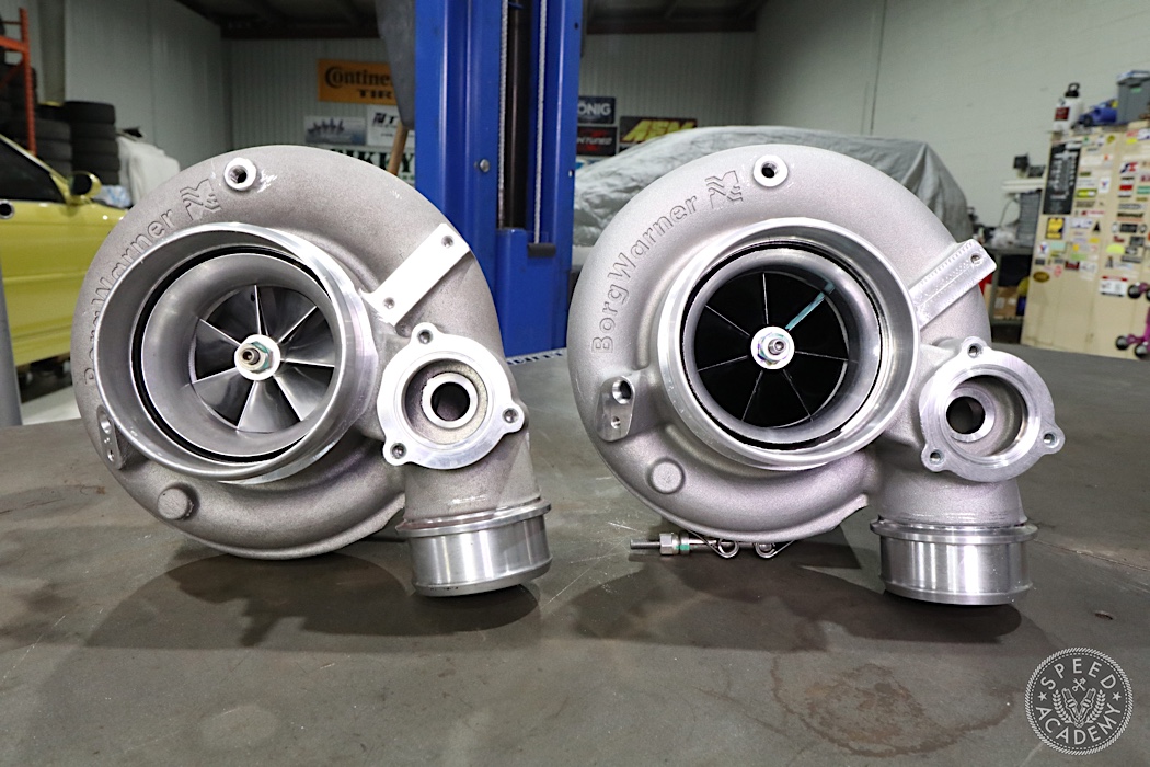
BorgWarner 9180 on the left and the new hotness 9280 on the right.
As some of you may have seen, I also got the new EFR from BorgWarner. I had been anxiously awaiting the release of the 9180 replacement for the past few years since, at my power level, I was right at the rev limit of the turbo and it’s not safe to overspin them.
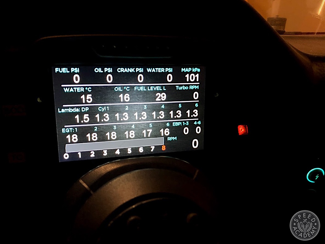
While building the manifold, a lot of other wishes I’d always had but had no practical way to implement, started bubbling back to the surface. One of them was that in the BMW FI community, there was always a suspicion based on failures and plug readings that the rearmost cylinder, #6, runs leaner and/or hotter than the rest. But the typical wideband placements post-turbo is just an average of all 6 cylinders. It’s useful for almost all situations but not if you have a cylinder doing something the rest aren’t.
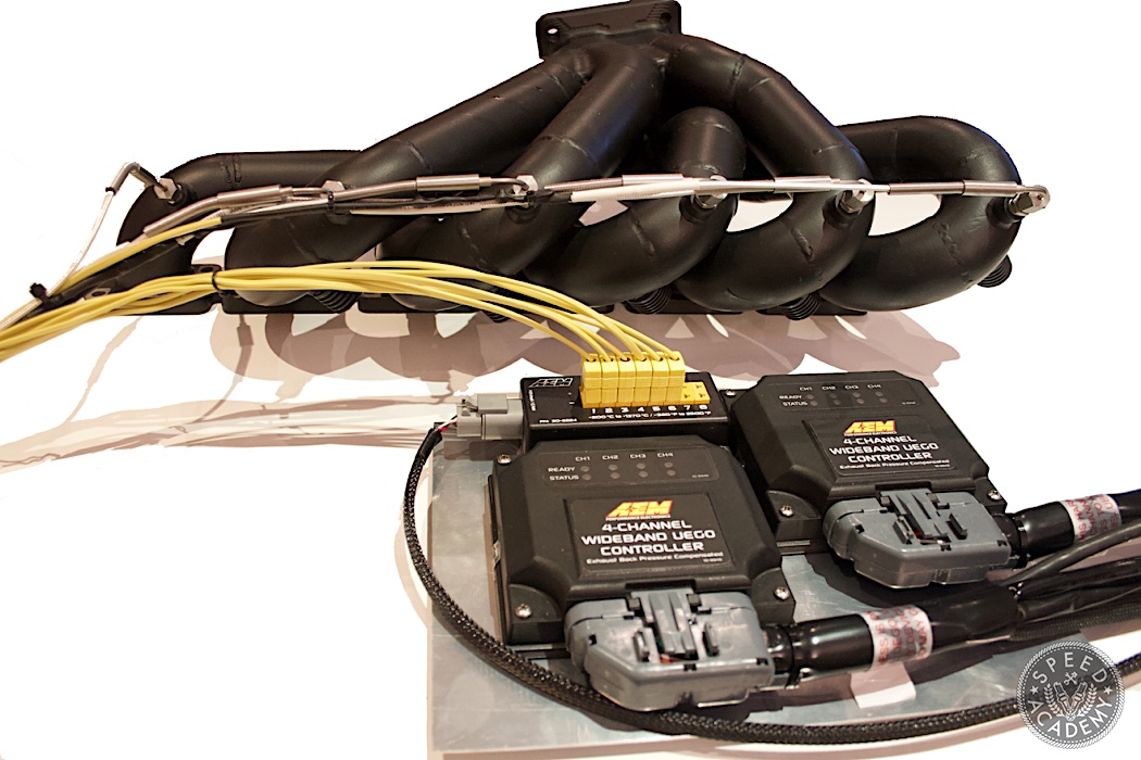
So I added bungs to the manifold and got more awesome AEM gear: two UEGO 4 channel controllers to go with the 8 channel K-Type EGT CAN module I already had, but now with EGT sensors in each runner.
Another bonus of the UEGO controllers was that they’d help me profile the 9280 turbo because most of the time we amateurs are just guessing about the turbo match to our engines based on some vitals. The BorgWarner MatchBot goes a long way to help you match their turbos to your needs, but while a very educated guess it’s still a guess without specific data. One of the parameters that tells a lot of the story is backpressure. Once the turbo manifold pressure starts getting higher than the intake manifold pressure, you are beginning to choke the turbine and the further you go past 1:1, the more inefficient your engine will operate – needing more boost for the same power, generating more heat etc. Idealists don’t want to see more than 1:1 but idealists don’t party.
Realistically, 1.8-2:1 is about the point where you need to look at changing things up, either going to a bigger turbo, turbine housing, larger exhaust, looking for other ways to make more jam at lower boost or backing off on your ambitions. My exhaust is a free-flowing 4” design welded up from Vibrant Performance parts, flanging out right off the turbo to a stainless downpipe and then titanium the rest of the way, so I didn’t foresee any restriction there but I wanted to know I’m not choking the turbo.
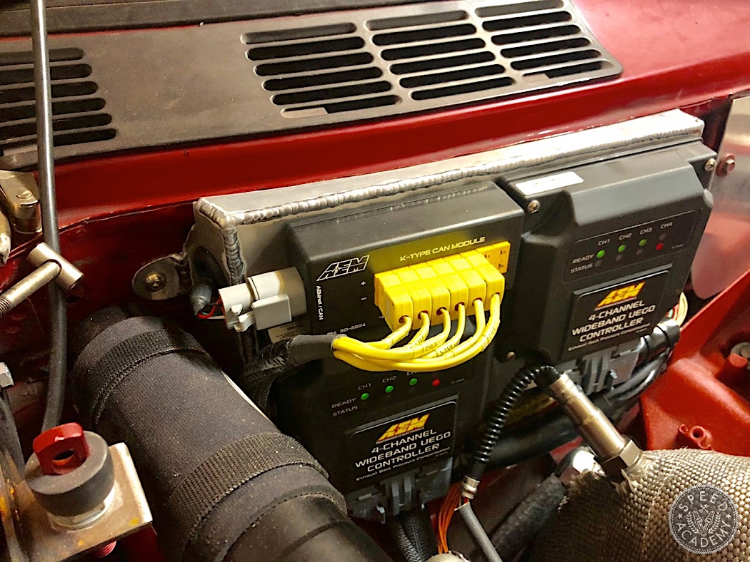
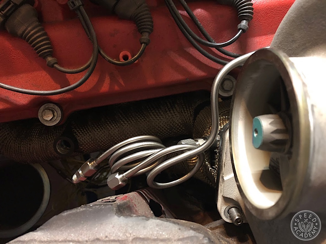
One problem with trying to measure AFR pre-turbo is pressure. The wideband sensors read inaccurately in a pressurized exhaust environment but the AEM UEGO controllers have exhaust back pressure or EBP compensation, which I also intended to use for measuring the turbo backpressure. You don’t want the sensors too close to the heat or vibration of the exhaust manifold, so AEM provides some plumbing, all of which needs to be used to keep the sensors happy. This took a little bit of planning but didn’t take long.
And of course, one of the best parts of using AEM gear, is that it all integrates so easily. To get the data, you simply connect the 4 pin DTM connectors and you have everything available on AEMnet. Then it’s just a matter of configuring your devices to use it. AEM provides all the CAN definitions for you, including predefined files by part number.
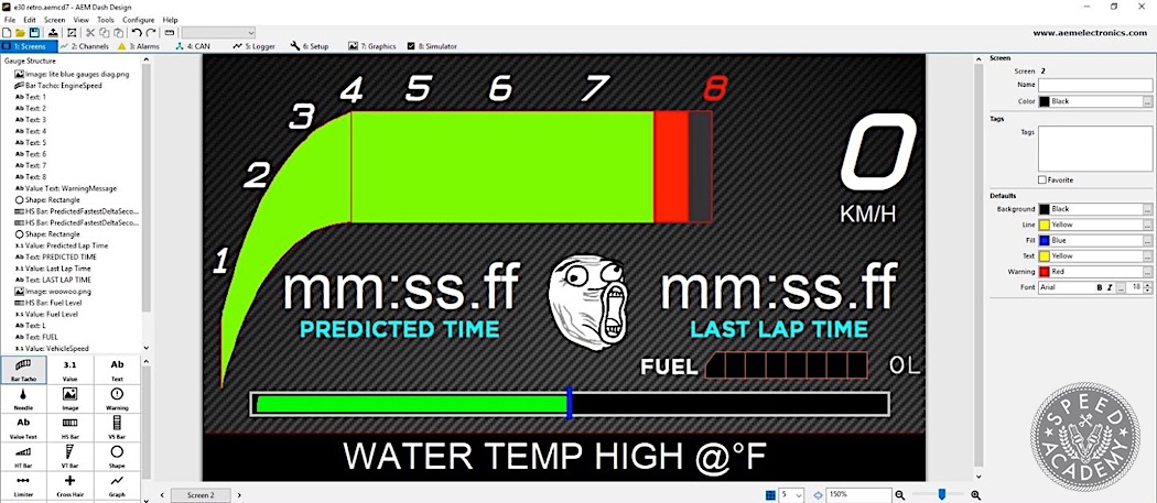
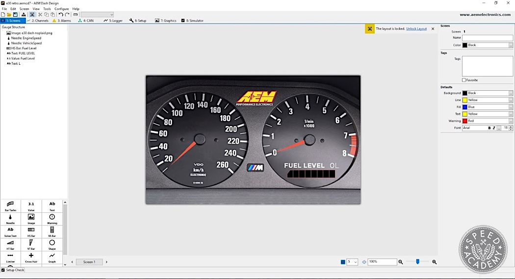
AEM also released their new DashDesign 2 and I got to play with it a lot. Pretty much everything that I was wishing for in 1.0, which I was actually a big fan of, has been addressed. Some of the biggest things that I like include the flatness of the CAN data configuration – rather than a separate tab for the CAN messages, another tab for CAN data processing and then another tab for assignment, all CAN definition is in one tab. And also the tabs, all of the major configuration views are arranged in tabs rather than having to navigate to a different menu and open a new layer. Plus the software will now render preview values. This saved me a ton of time because, for instance, my lap timer view has two tachs to form the shape so the labels are drawn independently and I used to have to guess approximately where they would need to go, and how much space to leave for things. Same for the angles of the dynamic needles over my retro dash page. In DashDesign 2 I could test the layouts and know how they would look before ever going to upload them to the car.
Not Silicon, Silicone…
While installing the BorgWarner 9280, I also decided to get rid of silicone couplers once and for all. To be clear, I am not saying there is anything wrong with the couplers or the T-bolt clamps. What’s wrong is me. I’ve had several blow-off and leaks and they were all my fault – failing to tighten the clamp fully, not having enough of a bead for them to bite on or the cruellest one of all was when I tightened the clamp over the 3 beads I welded on the edge so the car wasn’t building boost on the dyno but a low pressure boost leak test didn’t show anything. I later found it at home by pressurizing the intake to 10 psi and felt an air jet on my leg. The coupler would seal at low pressure but expand enough to leak around the beads at higher pressure, not holding more than a few psi. I had also removed enough skin off my head using these bolts while working under the car to have been formally scalped.
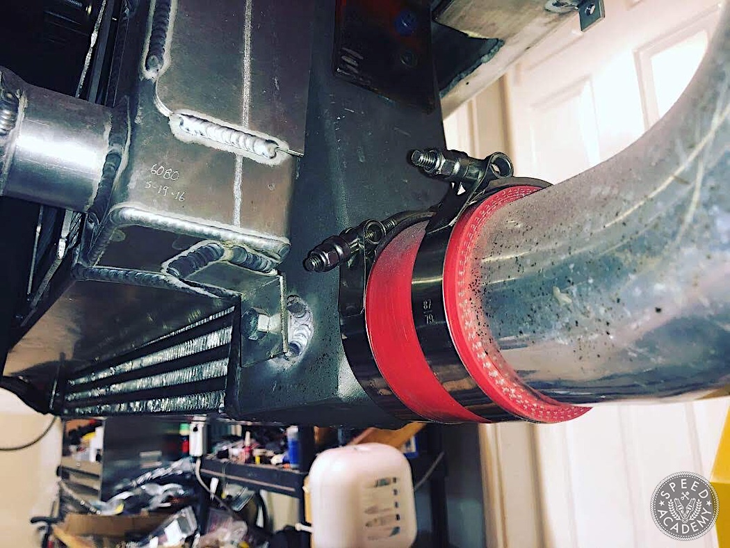
Enter Vibrant’s awesome HD clamps. They take the Wiggins clamp design and make it even better. Every time I demonstrate taking one apart to someone, they can’t believe it. There’s a pin with a spring loaded ball which holds the two sides of the clamshell together, so you press the release button, slide out the pin and the two halves swing apart. Then there’s a precisely machined ring inside the clamshell that seals the two flanges inside using o-rings on the flanges. The clamshell is only there to prevent the flanges from pulling out.