So you’ve done your homework, picked out your new toys and pulled the trigger. Now it’s time to get to work. OK, maybe admire it all a bit first… on the dinner table…for a few weeks. You gotta marry right to pull this off! #FeliciaForWifeOfTheYear
As we discussed in Part 1, if you went with one of AEM Performance Electronic’s plug-and-play solutions for your car and the appropriate configuration to go with it, there isn’t much you’d have to do to before heading to the dyno. But my E30, which my racer buddy Chris nicknamed ‘Das Hammer’, is so highly customized that there is no PnP harness or config that would do that for me.
But in reality, it’s not as difficult as you might think to do it yourself and it’s immensely satisfying. If you’re anything like me, though, the hardest part is getting started. When I was younger, I had heard about task and time oriented people but I thought it was a lot of touchy-feely woo. But through all of my hobbies and profession (software engineering, building and flying RC airplanes, powerlifting, all this car silliness, etc), I have gotten to observe people who very clearly belong in one group or the other and it made it obvious which one I was. Some guys are time-oriented and they are what I call “toilers”. Hey, read carefully! What I mean is that people like my dad are happy just getting to sit there and work away for as long as they can, stop and pick it back up later. This has never been me. Before I can start, I have to define a finish line. This means that if I can’t clearly state what I want to have accomplished when I pack it in for the day, I feel depressed and even feel physical pain at the thought of even starting.
Party On! Excel-ent!
When beginning this kind of project, MS Excel is going to be your friend. This is especially true if you are anything like me, because the wiring prep can be broken down into manageable tasks. If I may be so bold as to offer you some advice: document the crap out of everything!!! You will never regret it and I promise you that you will end up regretting not doing it, or wishing you burnt a few more calories doing more.
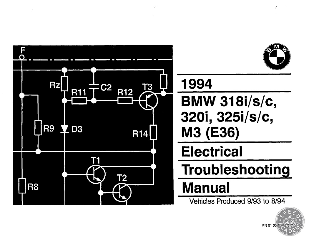
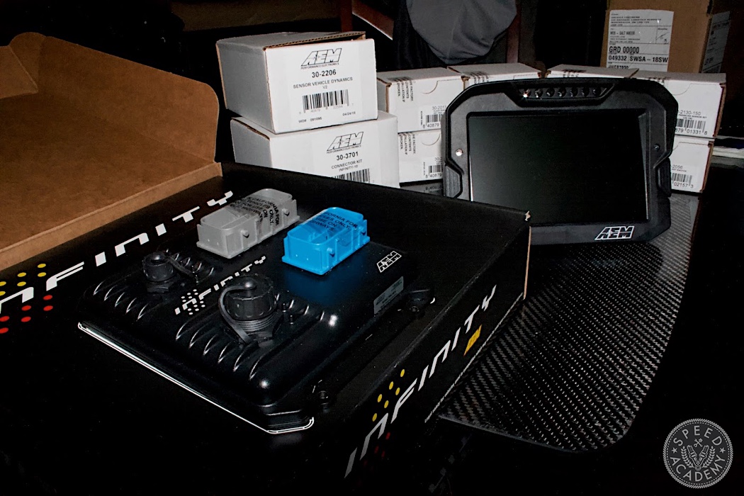
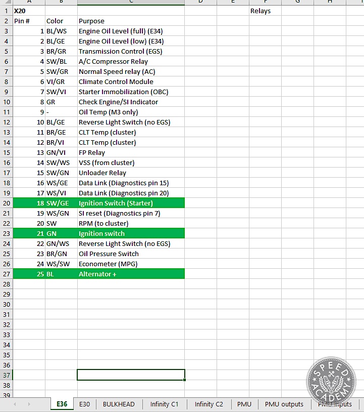
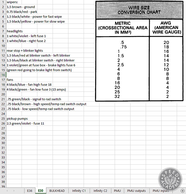
I started out by compiling every wire function of my chassis wiring (which is a hybrid of an E30 fusebox and E36 engine harness), VEMS, the AEM Infinity 708 and the PDM I decided to use (more on this later). Document everything first, and then highlight what you’re going to keep and why. This part is a bit time consuming, as you’ve got to find the electrical wiring manual for your car and dig through it. But they’re typically quite easy to use and understand once you get used to them. The first few pages usually explain all of the symbols and notations, so don’t worry if you’re not an electrical engineer. The best source for BMW ETMs is here:
http://www.armchair.mb.ca/~dave/BMW/
This one is better known and has a lot of manuals that the one above doesn’t but it has only one manual per car model and there are some subtle differences in model years that I’ve been burnt by before (e.g. my chassis is an ’86 which has a few differences from an ’87).
http://wedophones.com/Manuals/BMW/
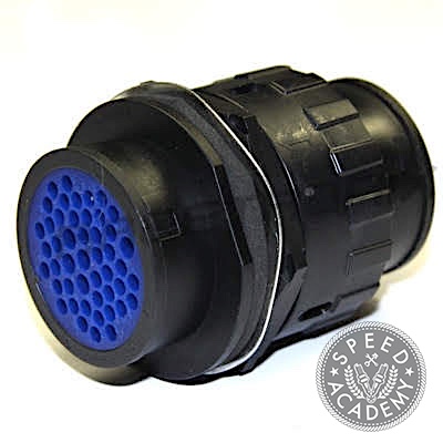
I wanted to separate the chassis wiring in the engine bay with a bulkhead connector, but the only ones that interested me are Autosport connectors and I wasn’t interested in spending a grand on the connector, pins and crimper for one silly bulkhead. My buddy and calibrator Sascha showed me a local company called Racetronix that sells a great quality 47-pin bulkhead connector for 77 bucks that uses normal Molex style pins. Sold!

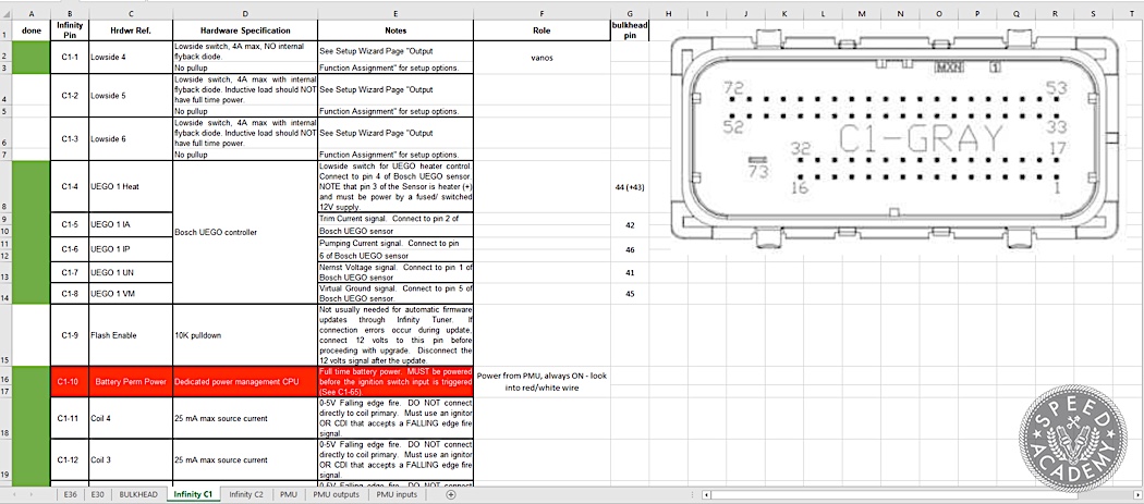
For the AEM Infinity connectors, I copied the pinout functions out of the manual and a snapshot of the connector and pasted them into the spreadsheet with a few extra columns for my notes.
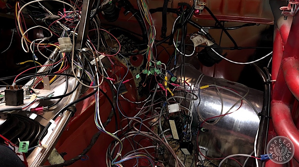
The reason why you see such details in the chassis side is that I was looking at all of the wiring I was going to be doing and how much more efficient it would be thanks to the AEM Infinity, as I described in Part 1, looking at the E30 fusebox and the power/ground wiring in the E36 harness was depressing.
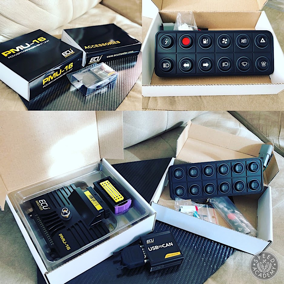
There are really cool products out there called PDMs – power distribution modules – which allow you to replace your entire fusebox with one small logic unit, with every relay and fuse and the related wiring being replaced by a single wire direct to the function (lights, wipers, starter, etc). I want to cover this in more detail another time since it doesn’t directly relate to engine management, but like the Infinity, until I learned about it, the only solution I was aware of that wasn’t a step backwards in some way was from big dollar Motec stuff and it was never going to be in my budget. But Sascha told me about the new PDM from Ecumaster, which also communicated over CAN and had CAN keyboard options, and I instantly knew I had to do this. The CAN inputs were fully user-definable so I would even be able to use AEM’s CAN messages to have it enable things like fuel pumps.
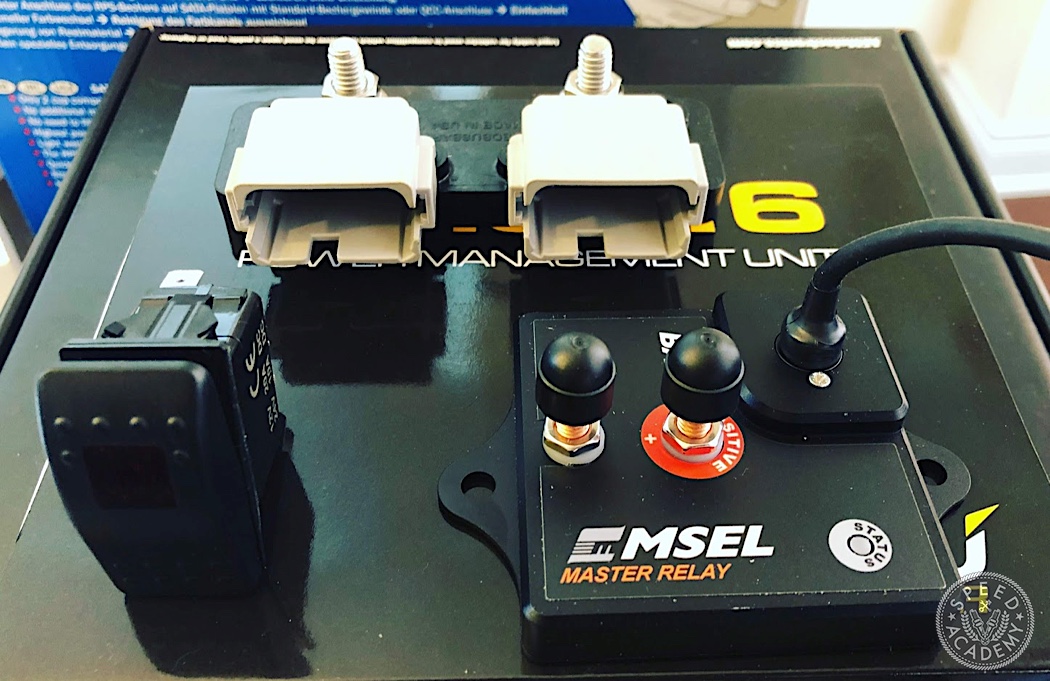
Around this time, I got an email from Gary at ARE who asked me if I’d be up for bringing my car to display in his booth at PRI. Now, I’m proud of my car no matter what stage of existence it’s in because it represents what I’ve learned to do up to that point. As a result, many things are in a transitional state until I can get around to it or learn how to do something better. And while Gary didn’t put any conditions on how my car would look, it made me want to do a lot of stuff that I wasn’t planning on doing any time soon. So in addition to the solid state power module, after some friendly encouragement from Sascha, I decided to pull the trigger on another item I had been drooling over, the MSEL master relay/battery isolator which is basically one giant solid state relay.
Something other (i.e. normal) people don’t seem to concern themselves with is their grounds, as long as they are reliable. Stacked ring terminal grounds had always bothered me and while I was going nuts with wiring, I wanted to do something nicer for the grounds too. I looked around for a bus of some kind but nothing really made me happy until I came across this guy: http://sealedbussbar.com/Product-Info.php
It was meant as a reliable power distribution solution for boats and such but I got one to use it as my ground hub.
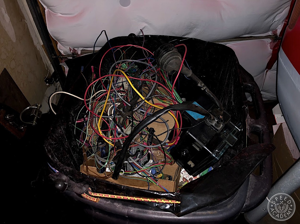
So this was the final resting place for my E30 fusebox…
Label Twice, Cut Once
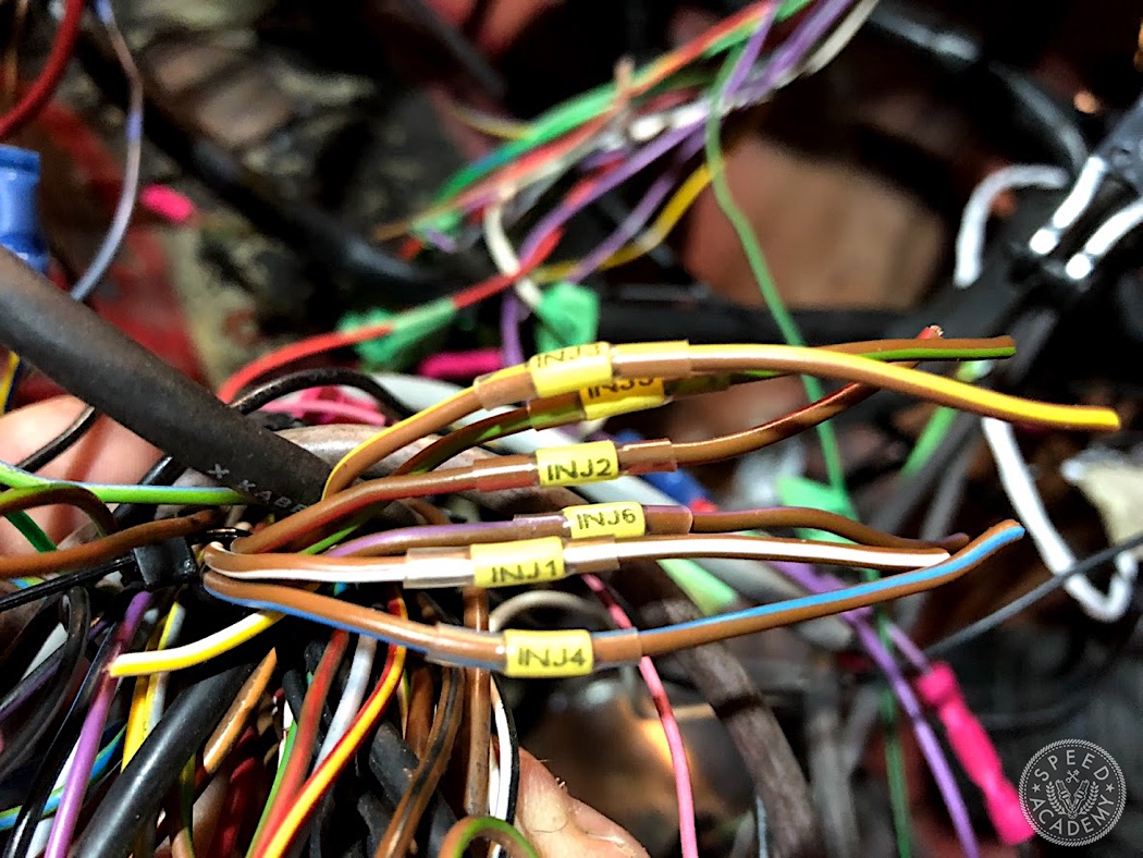
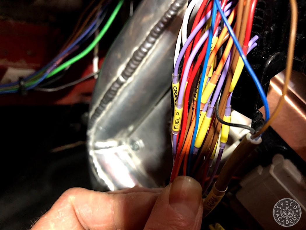
Something I learned from my previous wiring projects is that there is no such thing as excessive documentation, and this includes labels. This time I wasn’t just going to put some tags on key wires or ambiguous colors but document the role every single wire plays. Sascha loaned me his Rhino label maker and shrinktube label tape, and I got some clear shrinktube to go over it. After using it a few times, I got my own Rhino because it became clear how invaluable it is.
This sounds tedious and time consuming, but it actually didn’t take long at all. I was able to get each step done in an evening, which kept my task-oriented personality sane. Just don’t do too much at once, and it doesn’t hurt to verify the wire with a voltmeter (especially vitals like coils, injectors and triggers).
I mainly wanted to do this for future maintenance because I had enough experience trying to make changes to my bird’s nest you saw in Part 1. But this already paid dividends when I realized I made a mistake. For the sake of balancing the number of wires on one connector vs the other, I put the fuel pressure and water temperature signals on the C2 connector. The Infinity allows you to do anything you want with your inputs but there are predefined strategies, such as the calculation of the injector pulse width, which takes several things into account, including the manifold and fuel pressure – this way if your fuel pump or regulator start dying, the Infinity will increase the pulse width to get enough fuel into the cylinder. The engine protection and dash will tell you that your fuel pressure is going in the crapper so you can back off but in the mean time, your motor won’t fry.
These strategies are based on the signal from specific inputs, so I needed to move the fuel pressure and water temp signals to C1. Before, I’d need to look at my config to see which pin is assigned to the function, and start counting pins on the connector. And I end up repeating this a few times to be safe, because I’ve done the off-by-one thing a few times before. But now? Find the label, move the pin, done.
Crimp It and Rip It
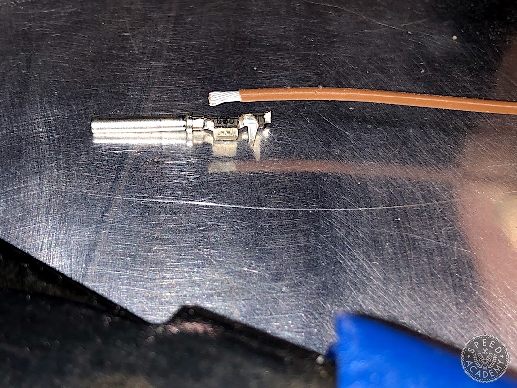
Next, you have to crimp the pins onto the wires and stick them into the connectors. There are different kinds of pins and crimpers but the most common, and my favourite, are the Delphi/Molex style (that’s how I know them, anyway). The terminals themselves vary, but the crimping method is the same. This is a pin for my coolant temp sensor, the AEM Infinity pins and various others are the same idea: there is a U channel for the conductor, and another U channel that grips the insulation.
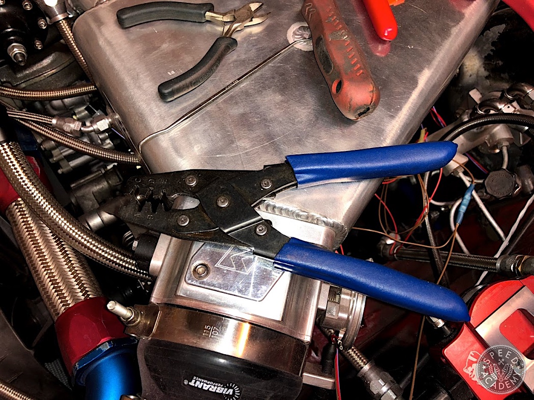
For the crimper, there are fancier ones you can get but this one has served me well, for the Econoseal VEMS connectors, Weatherpak kits, Bosch connectors and now DTM and Molex. It works great and you can get one for under 40 bucks on eBay. I am probably now in a legal common-law relationship with this guy, due to the amount of time we’ve spent together.
Pick the slot that most closely matches your pin and put it inside until it bottoms out. Then put the wire in so the insulation is right up to this first channel.
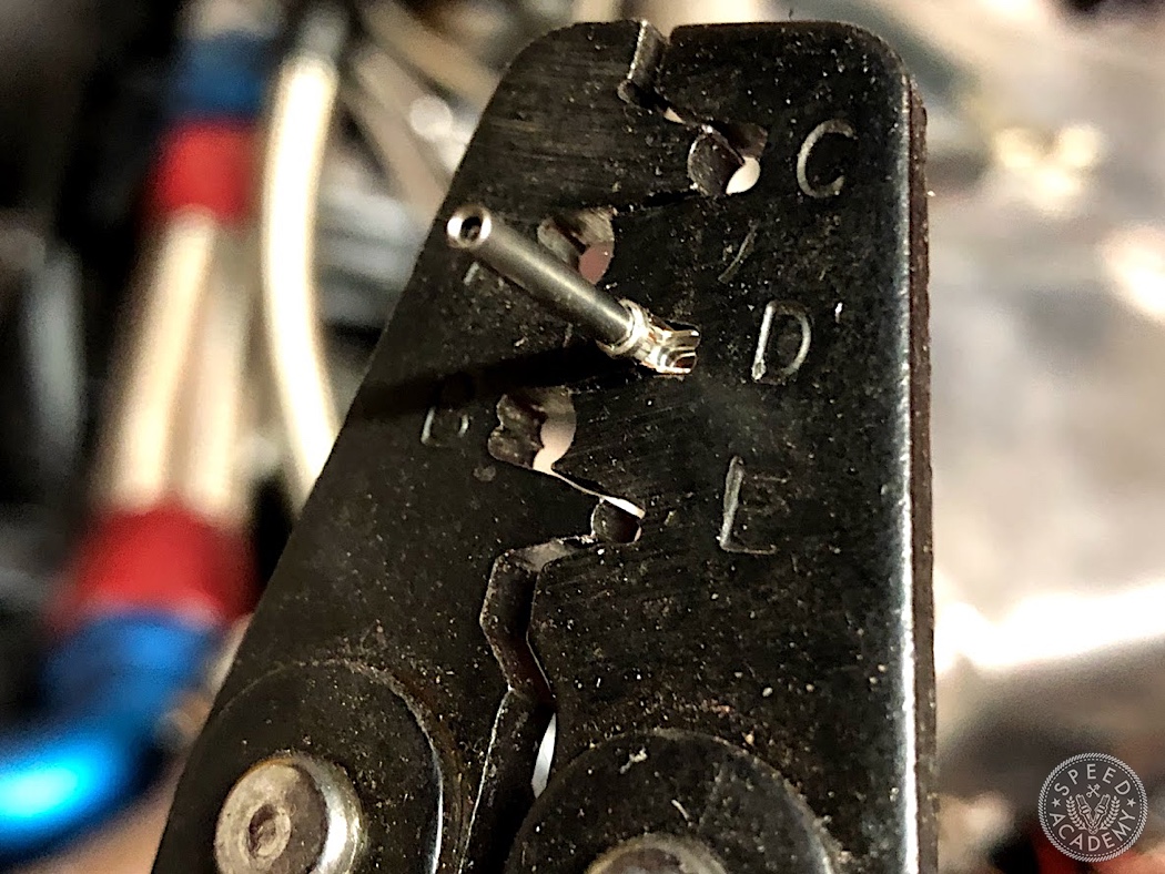
Give it a good tight squeeze, you can feel it sort of bump past a resistance, this is the U channel wrapping around and pinching down onto the wire. Crush it down some more, take it out of the crimper and give the wire a couple of solid tugs. If it comes out, you probably used a crimper slot that’s too big. You could have also picked a wire that’s too small for this pin. I’ve had this happen when I was using super thin signal wires and what I do is strip them 2-3x too long and fold the stripped wire a few times to make it crimp tightly.
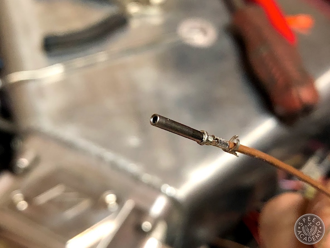
You can see here that the insulation U is already bent a bit. That’s because before doing the final crimp, I like to first get it started in a larger slot of the crimper because it’s usually a lot more fragile than the conductor U, and rather than wrapping around, it might want to bend back or do other weird things.
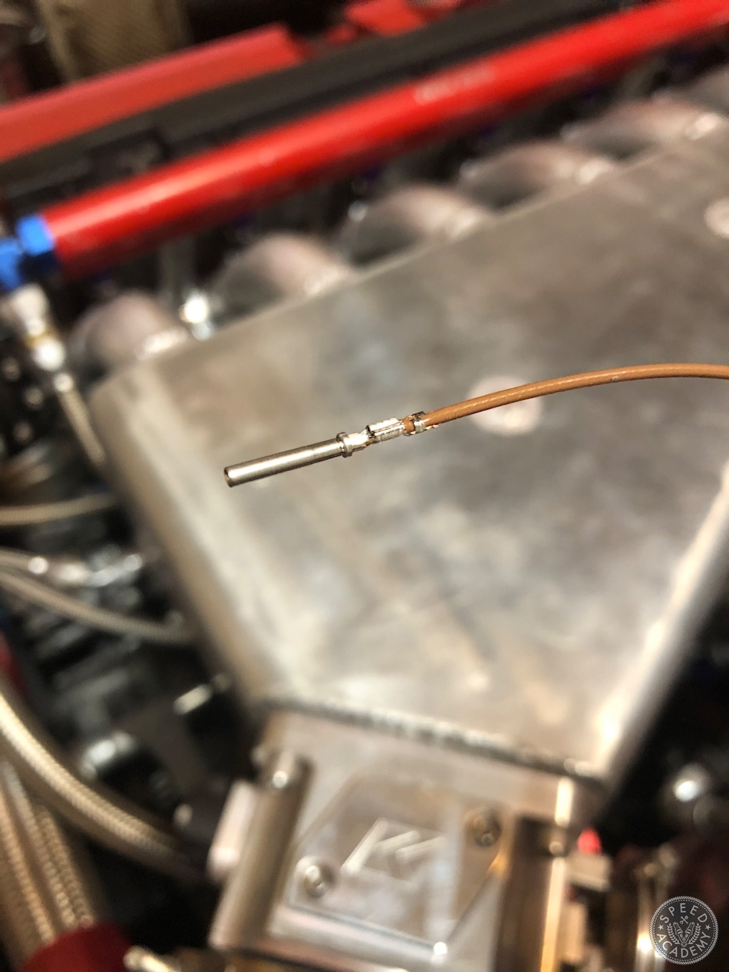
Once you’ve fully crimped it down (image above), just slide the wire into the hole you want to use on the connector. Mark your spreadsheet that the pin is done, and… repeat this a hundred times.