I chose to go with ARE, who have been doing this for longer than I’ve been alive and have evolved their products to an impressive level. ARE systems are trusted by everyone from people like me to professional teams like Corvette Racing. Oh, and NASA. The operation is also completely and proudly American. Gary and Sandy Armstrong are extremely patient and polite, always willing to help guide the customer with their project even though they would be fully justified wanting to keep this lifetime of experience secret. It also helps that they are an absolutely delightful team, always making me feel like we’re long time friends.
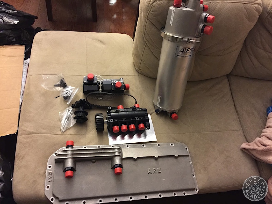
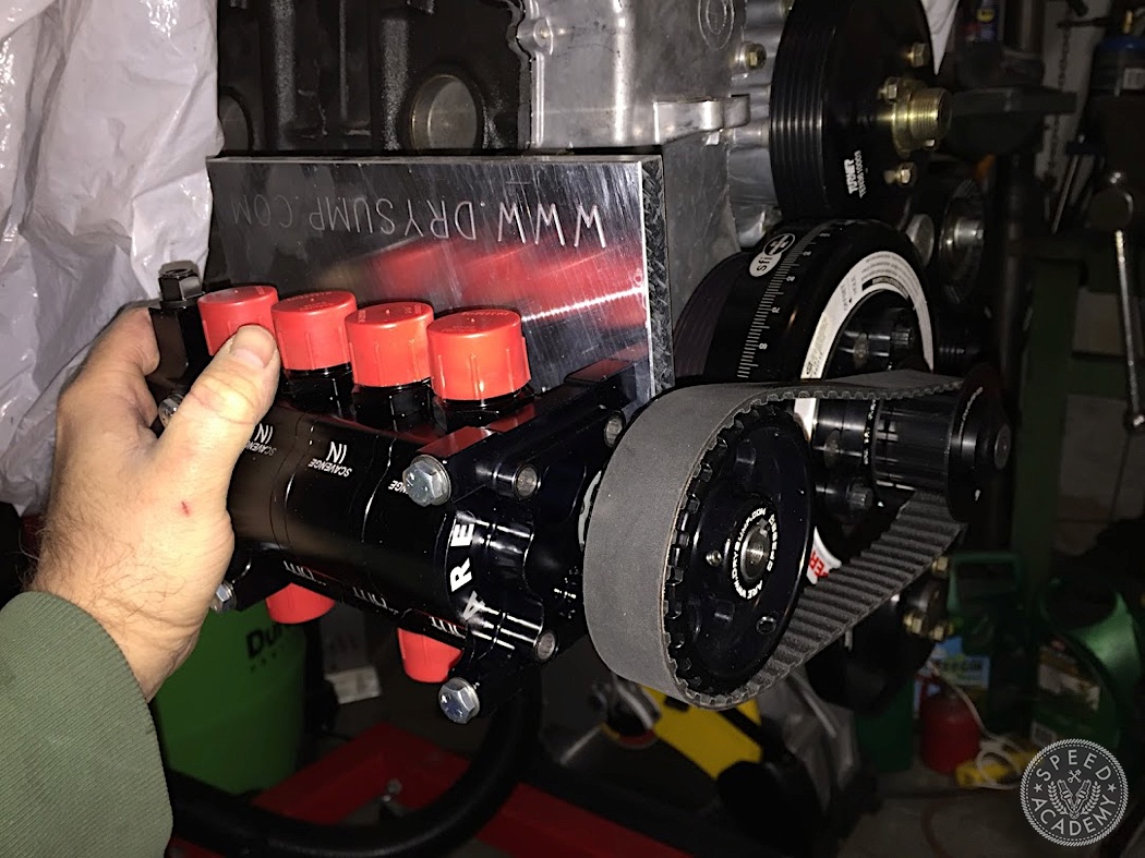
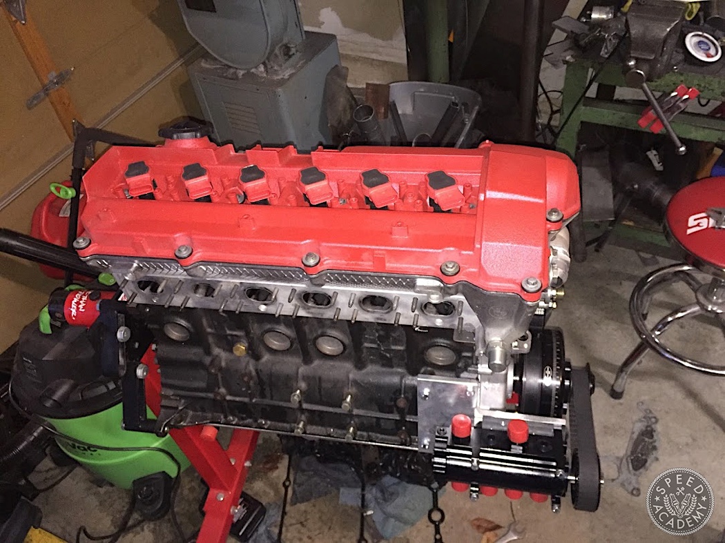
ARE makes really beefy oil pans that are cast like an OEM, with proper scavenge “sump” designs and baffling. I decided to go with a 4 stage pump (remember, that means 1 pressure and 3 scavenge stages) and a corresponding 3 scavenge pickup pan.
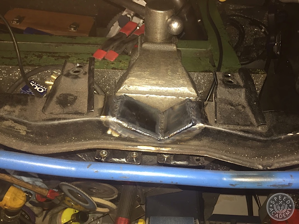
The pan is designed for the motor in its native home: an E36. My E30 has the engine crossmember and steering rack much further back. Dry sump oil pans are very flat so this wasn’t a huge issue but I notched and welded my crossmember to clear the pan so I could also put the engine a little bit lower.
I removed the stock oil pump and bolted up the pan.
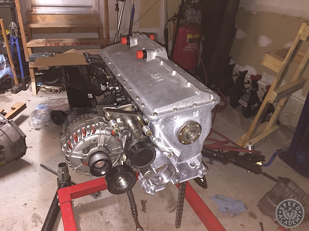
To mount the pump, Gary sent me a mounting plate that is designed to locate the pump in several possible orientations and then cut to fit a suitable mounting location. I chose the 4 AC compressor bracket holes. I have since sent Gary the dimensions of my finished bracket so it should soon be available as a pre-made piece.
A subject for another day is the crank damper. It is also a very poorly understood subject. Some people think it is just a nuisance that makes changing timing belts hard for no reason, and is there to trigger the crank sensor and spin the accessories. It actually happens to be a vital part of the engine: a tuned mass suspended on a rubber ring, engineered to damp the harmonic frequencies of the crankshaft. The quick and dirty visual to have in mind is to picture a foam pool noodle as your crankshaft, and each con rod trying to twist it. The twist eventually gets transmitted to the flywheel but not without the noodle loading and unloading from the twisting of each power pulse, with the effect being magnified as you move to the front of the engine (which is why the front main bearing gets beat up the worst). Without a damper for the right frequencies where this is most violent, the engine will beat itself to death and the more powerful the power pulses, the more mass you need to damp the front of the crank. The damper itself needs to be rugged since the energy is stored and released by the rubber in the damper. The PTG BMW racing team, limited by the rules, had problems with the stock dampers not lasting a race. They cured the problem by directing cooling air over the damper – that should give an idea of how much energy was being stored in them!
If you want to nerd out further, read this.
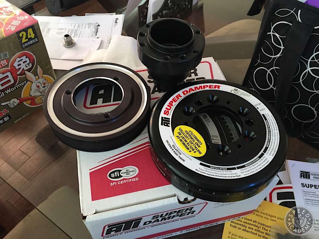
Anyway, I got a giant damper spec’ed from ATI, designed for up to 1200hp. It’s so big that it doesn’t fit behind or inside the accessory pulley of the M50 so the mass sits in front of the pulley.
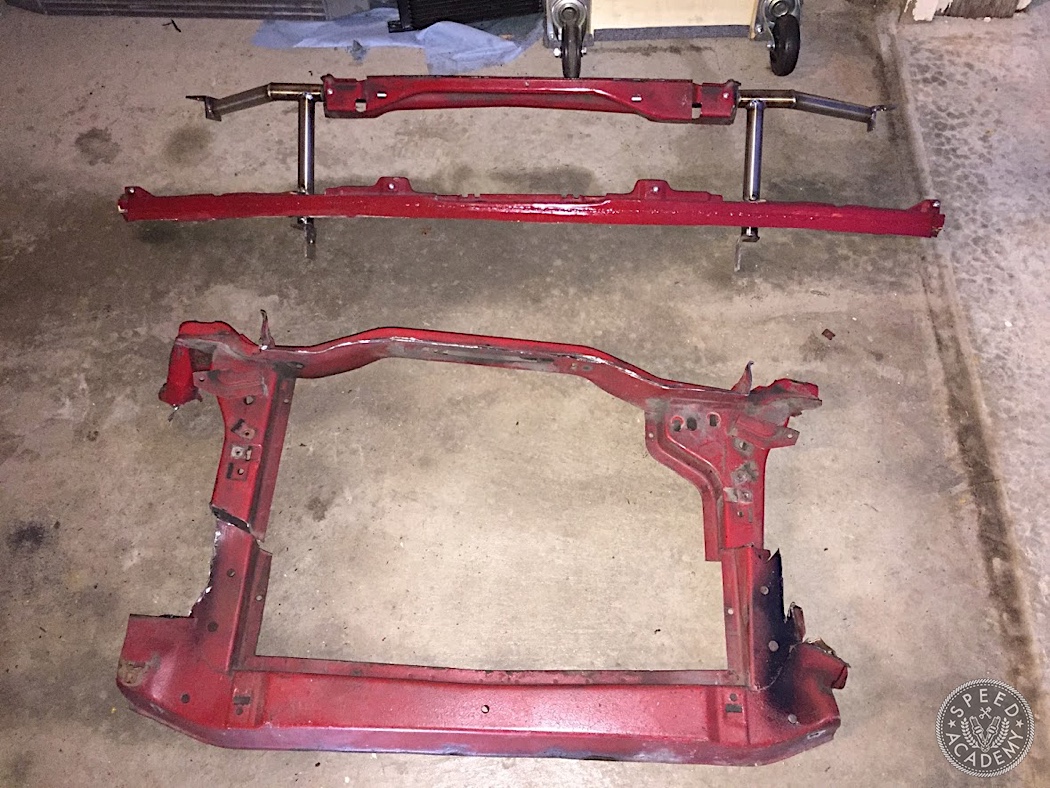
I anticipated that this would intrude on the radiator because the E30 engine bay is much shorter than the E36. I cut out the radiator support to make a removable one, and mount the radiator right up against the grille. I also installed a giant C&R radiator based on a PWR extruded tube core, converting all fluid connections to AN… but that’s for another time.
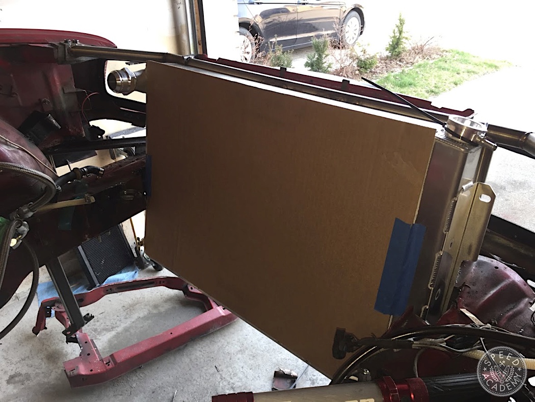
With the engine out, I tried to do my best to get an idea of where the engine will sit relative to the radiator and all of my measurements pointed to a possible collision course. I looked at pictures of my car showing the firewall and it looked like I had about ¾” to the firewall. I hated the stock aluminum motor mounts and they always bothered me for this power level with solid engine/trans mounts, so I decided to take the opportunity to make my own out of heavy wall steel, ½” plate and ⅜” wall tube. These would relocate the engine about a half inch back.

This miraculously proved to be perfect, leaving a little breathing room to the firewall and clearing the radiator. Not by much but enough, even leaving enough room to be able to slip the belt off.
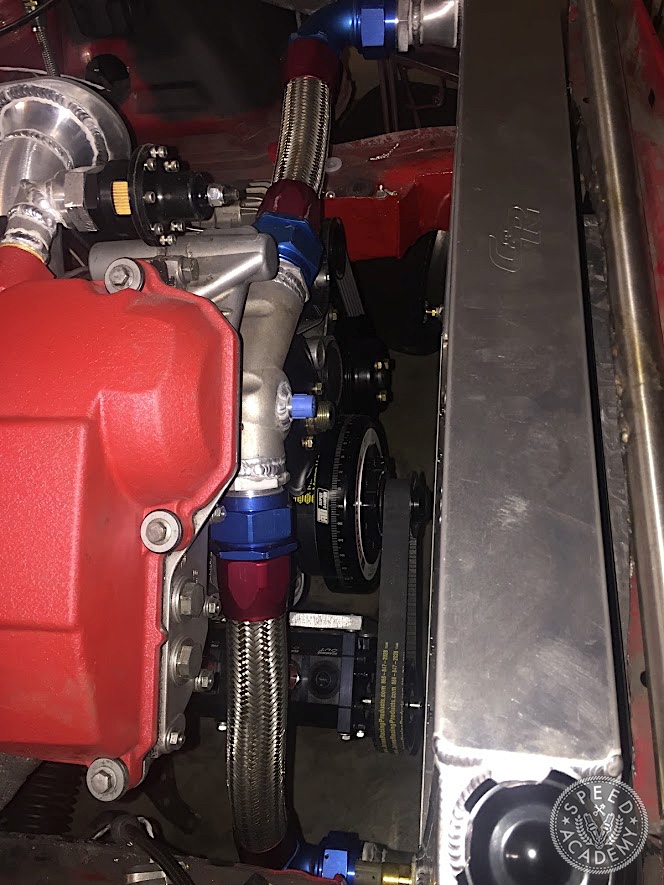
With the damper installed, I bolted the ARE drive mandrel to it, bolted the pump to the plate and started measuring for positioning on the bracket. Once this was determined and squared up, I measured and sent Gary the center-to-center distance from the pump shaft to the crankshaft. This would determine the length of belt I needed. You don’t want it to be loose for obvious reasons but you also don’t want it to be drum tight. The general rule for this drive belt is that it should be difficult to twist it 90 degrees.
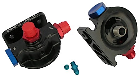
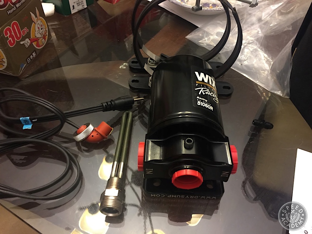
The pump would feed ARE’s gorgeous billet filter mount.
The big remaining question was the location of the tank. I got ARE’s biggest tall design tank and the Spintric. I got a pile of different Vibrant hose ends and found a combination that would allow the Spintric to sit on the tank with clean/compact hose routing.
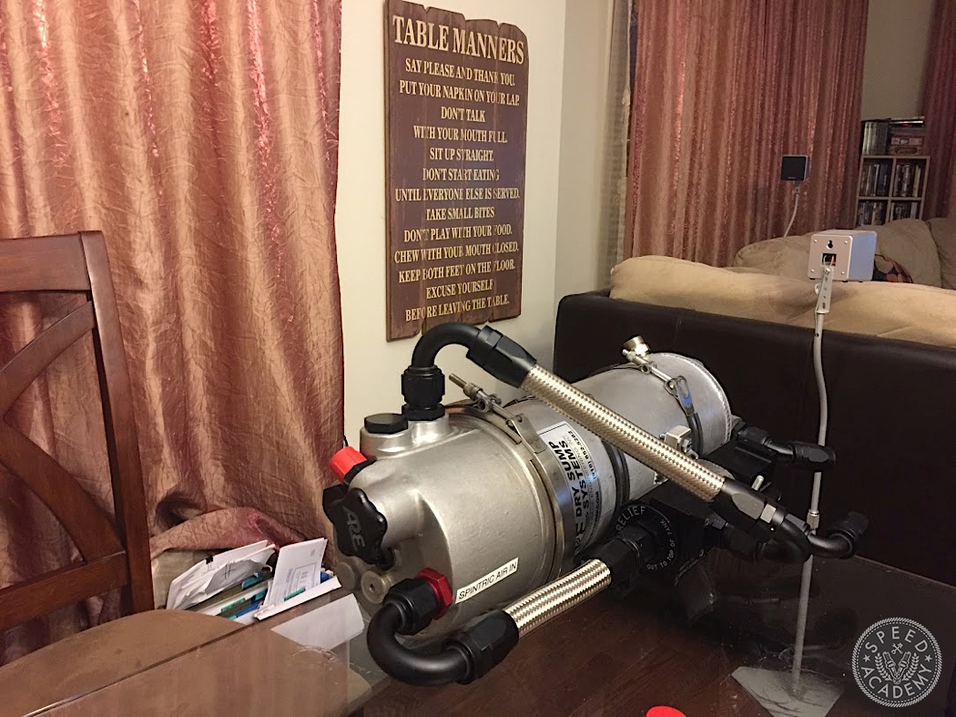
But it would present a challenge to fit it into a squatty 80s German compact. I tried various locations in the interior but none made me happy, both from a safety perspective and a maintenance nightmare. Oil changes with dry sump should be made easier not harder than stock.
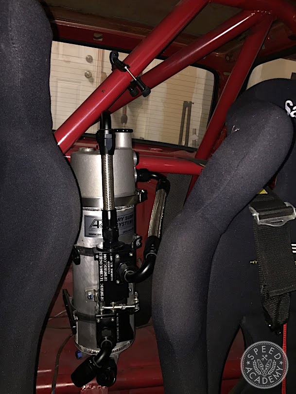
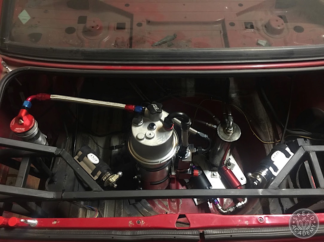
I settled on the trunk. I already have the main fuel pump and surge tank in the spare wheel well so the oil tank would be a welcome addition. It would also move a pile of weight, statically, to the far end of the car, balancing out some of the heavy additions at the nose.
I also installed ARE’s new patented design catch can, being careful to ensure a steady incline of the vent line.
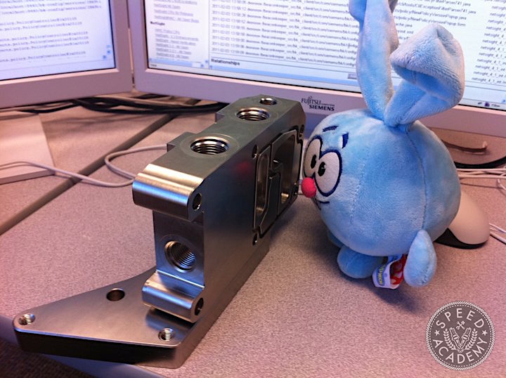
Supplying the motor was the easy part because during the initial turbo build, I used VAC’s billet filter delete block, and used a remote filter and oil cooler. It’s a great piece, allowing for an easy addition for a classic spin-on filter mount and oil cooler, as well as providing ports to easily add oil pressure and temperature sensors.
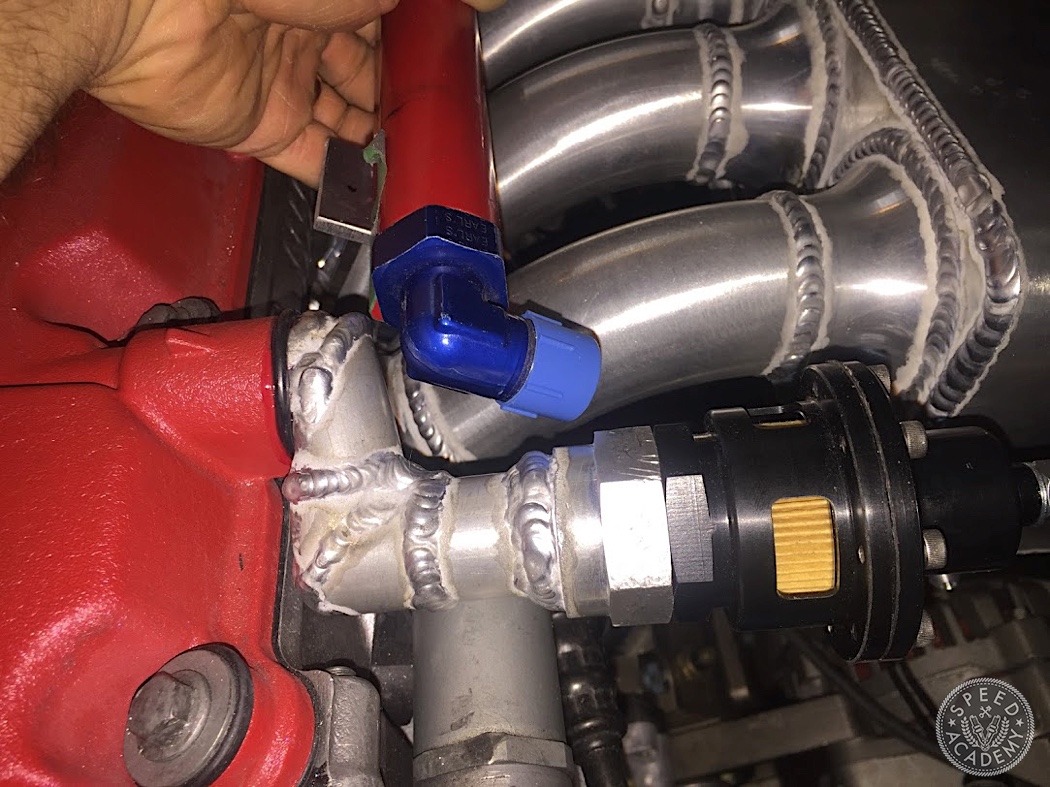
Something Mike McGinnis of COBB Tuning pointed out to me was that I would need to do something to control vacuum. These pumps are so good that without the blow-by, in other words at low loads/revs, the scavenging creates an excessive amount of vacuum and you can suck in the seals. So I added this part from Peterson which acts like a reverse blowoff valve, opening when the vacuum is too high. I set it to around 7 psi of vacuum. I don’t want to discuss the elbow because it took several very annoying iterations. I cut that stupid thing apart and re-welded it many times until it finally sat without hitting anything (and I would only discover that things wouldn’t fit as I assembled them, having to go backwards and redo it).
With the engine installed and hoses routed, it was ready to test. I spun the pump by hand until I could clearly feel the change in resistance, meaning that it was pushing oil. Now it was time to crank it. For oil pressure I had an old school mechanical oil pressure sender and gauge from VDO. I know from before that these don’t usually register anything much below 10psi so when I cranked the motor and didn’t see a pressure reading, I wasn’t hugely concerned. So I tried starting the engine. It idled around 12psi. This was disappointing as I was hoping to be able to raise the whole spectrum. 10-15psi is about what these engines idle at hot when stock, with the high pressure bypass opening at around 60. I wanted over 20 at idle and 90-100 peak.
I replaced the sender and gauge with a digital pair from AEM Performance Electronics but they confirmed the readings. Revving the motor did make the pressure go up at the typical 10psi/1k rpm. Idle pressure doesn’t really matter but it just didn’t make any sense. Maybe I needed a different drive ratio? But my drive ratio was picked by Gary and having looked at other people’s setups, it was very sensible as expected, in fact many had a lower ratio (lower speed pump drive). So I kept digging. I tried bypassing the oil cooler in case it was somehow plugged with an ant farm. I got another brand new filter. I changed the supply hose from the tank to the pump from -12 to -16, which is a good idea regardless as it’s a long way to draw the oil, although I do have a heater. But nothing changed the pressure.
One night I was bugging my friend in Minnesota who built my bellhousing for the 4-speed swap and he was bored on a long drive from a track event so he called me to bounce ideas around. We discussed things like the oil squirters (which my engine builder forgot, but I put in when I rebuilt the engine that winter) or a gallery plug falling out. None of it added up.
Finally he asks, the way you ask someone calling tech support if they’ve actually plugged in the device, if I plugged the OE pump reference port. What is that, I asked. He said the pump has a large pressure reference that comes from the main gallery which is used to open the bypass. I had assumed that the bypass was self-contained, so if the pump generates too much pressure then the valve opens and the pump vents back into the pickup or the pan. He explained to me that this would decrease the pressure in the engine as your filter becomes blocked, so you want the pump to generate enough pressure to produce the desired pressure in the main gallery.
D’oh.
Thanks to the compactness of the dry sump pan, I was able to unbolt it and slide it out of the way enough to expose the giant (at least ¼” ID) oil pressure vent I left in the engine. In hindsight, this is an accidental demonstration of how good the ARE pump is, being able to maintain good (OE or better) pressure with that much loss.
I carefully tapped the hole for ⅛ NPT and put in a plug with permanent loctite (not red, the hard core green stuff).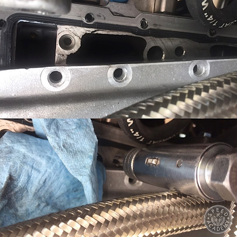
Cranked the engine and instantly it showed over 40psi cold (not really cold as I would get the oil hot with the heater). As the oil got to operating temp, my idle levelled out around 30. That’s more like it!
At the track, the oil pressure in the logs might as well be the tachometer and the temperature stayed perfect. I couldn’t be happier with the result! This year I’m going to bump the peak pressure to my desired 100 (currently around 85) but first I need to swap out the oil pressure gauge as in the BMW world you don’t expect to ever need over 100.
And it’s just that easy.