So that’s how the Wankel rotary engine was born and eventually became synonymous with Mazda. But how exactly does a rotary engine work? There are some excellent videos on the Interwebs that illustrate how this unique piece of engineering comes together including the above example, but since I like to abuse my keyboard, here’s a quick overview of my own to explain things in a bit more detail.
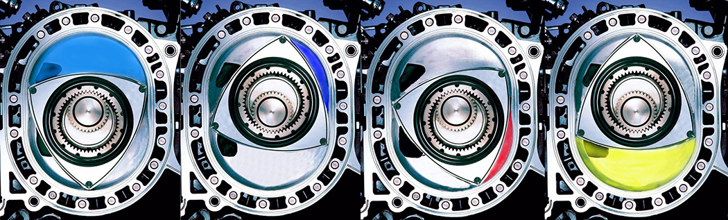
The four stages of combustion, starting with the intake charge entering the rotary housing via the intake port (light blue), the intake charge being compressed (dark blue), the compressed air/fuel mixture igniting with the aid of a spark plug (red), and the by-products of combustion exiting the exhaust port (yellow).
At the heart of a rotary engine is a trochoid-shaped rotor (looks a bit like a bloated triangle), which spins on an eccentric shaft within an oblong or cocoon-shaped rotor housing. This design results in three spaces between the rotor and housing wall, creating the required chambers in which the four parts of the combustion process (intake, compression, ignition, and exhaust) take place.
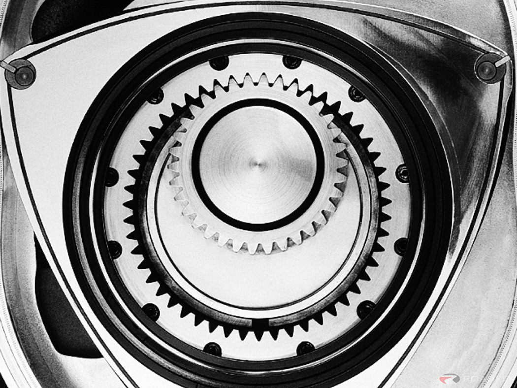
The larger diameter gear inside the rotor provides a 3x multiplier effect to the speed at which the eccentric output shaft spins.
Part of the genius of the Wankel rotary design is the way in which the eccentric shaft interfaces with the rotor. There is an inner-toothed gear ring fixed on the inside of the rotor and an outer-toothed gear fixed on the eccentric shaft, with the turning speed between the rotor and shaft being 1:3. In other words, the rotor rotates once for every three revolutions of the eccentric output shaft. What this means is that with the engine running at 9,000 rpm the rotor itself is only spinning at 3,000 rpm. This allows the relatively small displacement of say the 13B two-rotor engine featured in FC and FD RX-7 (654cc per rotor for a total displacement of 1.3-liters) to produce very impressive peak horsepower figures. It’s this RPM overdrive or multiplier effect from the way the rotor interfaces with the eccentric shaft that creates such tremendous volumetric efficiency from these compact engines.
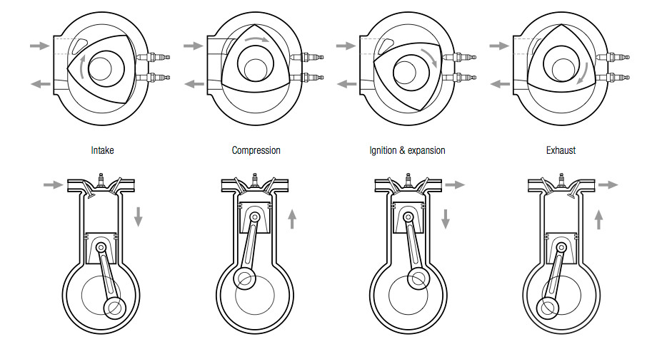
A comparison of the combustion cycle of a rotary engine (top) and a piston engine (bottom).
The output shaft multiplier effect is also part of what makes rotary engines feel so smooth and quiet compared to a traditional piston engine. During a single combustion cycle the eccentric output shaft of a rotary engine spins three times and the rotor itself completes just a single revolution of the rotor housing. Meanwhile, in a traditional piston engine the crankshaft (output shaft) makes two full revolutions to complete a single combustion cycle and each piston travels up and down its cylinder three times. The very high piston speeds that result from this, along with all the additional moving parts in the cylinder head(s), means there’s a lot more noise and vibration produced by a piston engine as compared to a rotary engine.
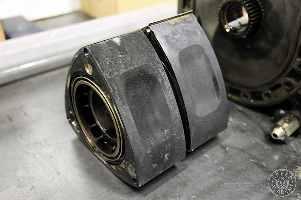
9:1 REW rotor on the left, 10:1 Renesis rotor on the right. Note how shallow the combustion cavity is on the Renesis version compared to the REW version.
And what about the rotors themselves? How do they determine compression ratio, and what other design features do they have that impact on the way a Wankel rotary engine produces power? Well, since the three faces of each rotor seal off the combustion chambers with the help of the apex seals (just like the pistons and rings seal off the combustion chamber within each cylinder), the dish or cavity on the rotor faces is what determines compression ratio. So in a 13-REW out of a turbocharged FD RX-7, the deeper cavity increases the volume within the combustion chamber and thus reduces compression ratio (to 9.0:1), while the shallower cavity of the naturally-aspirated RX-8 13B Renesis rotor raises compression to 10.0:1.
Weight is an important consideration with rotors, where even a small reduction in mass will pay big dividends in terms of engine response and maximum RPM the engine can safely reach, not to mention adding reliability by reducing centrifugal forces. The 13B-REW rotor, for example, is designed to be strong enough to handle the higher combustion pressures and gas loads that come with turbocharging while still revving to an impressive 8,000 RPM, resulting in a weight of 9.7 lbs. Meanwhile, the Renesis 13B doesn’t need quite as much strength in its rotors since its naturally aspirated, so weight has been reduced to 9.2 lbs and the rev limit raised to an astounding 9,000 RPM. I took things a step further by using Racing Beat 9.0 lbs Renesis rotors and Mazdaspeed race bearings in the RX-8 engine Joe Ferguson built for me so it could be safely revved to a motorcycle-like 10,500 RPM! Brap Brap! Check out the above video for what that sounds like while ripping around Toronto Motorsport Park.

As Jim Mederer from Racing Beat (a highly respected rotary engine tuner) explains on his website, “Bearing loads in a rotary engine are primarily the result of two forces – centrifugal force and combustion gas loads. At low RPM, gas loads are the majority of the total load on the bearings. However, at high RPMs, centrifugal loads predominate since they increase proportional to the square of the RPM. Since it is desirable to continue to use most or all of the stock RPM range, the only way to decrease that bearing load is to reduce the mass (weight) of the rotors.” And since boost pressure via supercharging or turbocharging always increases gas loads, anything you can do to reduce centrifugal loads is guaranteed to improve bearing life and reduce flexing of the eccentric shaft, both of which are known issues once you really start to lean on these engines.

Another key area on rotors is the apex seal seats. The groove at the tip of each point of the “triangle” is where the apex seals sit and are pressed against the rotor housings via spring pressure beneath each seal. It’s a very clever design, since as the seal wears the bow-shaped spring continues to apply upward pressure so that proper contact is maintained between the seal and housing surface. But as the seal is pushed farther up by the spring, it becomes less and less stable in its seat, which can lead to chattering or even total loss of compression as the seal is literally peeled out of its seat. The turbo 13Bs use a deeper seat and a taller 3mm seal (in either 1-piece or 2-piece designs) for greater stability and strength, while the Renesis uses a shallower seat and 2mm seal to reduce weight at the tips of the rotor where centrifugal forces are highest. We EDM wire cut the seats on our lightened Renesis rotors to allow the use of stronger Goopy Performance REW 3mm seals, in anticipation of adding some boost pressure (which we eventually did with a Pettit supercharger).
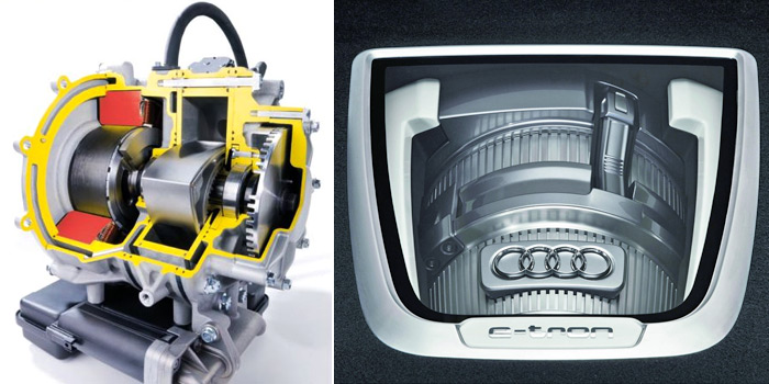
The Wankel rotary engine really is remarkably simple and elegant in its design. There are far fewer moving parts in a rotary than in a piston engine, but because they’ve never been the most reliable or fuel efficient, nor the cleanest burning, Mazda no longer produces a vehicle powered by a rotary engine and it’s entirely possible we won’t see another mass-produced Wankel as emissions and fuel regulations get stricter and stricter. Audi has breathed a little new life into the Wankel design, though, using a tiny single-rotor motor as a generator to charge the batteries in their E-Tron hybrid concept. The compact size and quiet operation of a rotary engine makes it very appealing in this sort of application, so perhaps this is what the future holds for Dr. Wankel’s mad invention.

Awesome post! Great insight into Jim Mederer’s rotary tuning.
BrianCan I concur, although I fear that I am biased towards the Rotary engine 🙂
Excellent write up as always !