How?
Since we’re not going to be making any parts, all that’s left is to make sure that what we have is the right size. This obviously requires that we first know what the right size is. Your pistons will say what bore they are meant for, so we can verify that the machining was done correctly. The same goes for the clearances of the rod and main bearings. And while I concede that it’s not strictly necessary, I prefer to even check the wrist pin clearance. These things take a little extra time but it all but guarantees that when you hit the ignition for that first start, it will just work.
For the bearing clearances, the general rule of thumb is 0.001” per inch of journal diameter. This is generally on the looser end of clearances, especially for narrower journals like BMW’s. Tighter clearances are more efficient, resulting in fewer losses so they are favoured by naturally aspirated motorsport applications. But if you’re building yourself a turbo motor, you have HP to spare, so a little loose is better in my opinion if you can supply the oil reliably and my ARE drysump sure can.
The M50 journal diameters are about 59.98mm and 45mm for mains and rods, respectively, or about 2.36” and 1.77”, giving us a bearing clearance target of 0.0023-0.0024” and 0.0017-0.0018”. I will be happy to end up around 0.0022-0.0024” and 0.0020-0.0022”. For reference, as an example of what I mean in terms of what’s acceptable – BMW spec for the mains is 0.0008-0.0023” and for rods, 0.0008-0.0022”. 0.0008” will leave no room for any issues and will make the oil work hard to evacuate the heat but it will make the oil pump’s life a lot easier. I was told that BMW Motorsport spec is 0.0008.
Tools
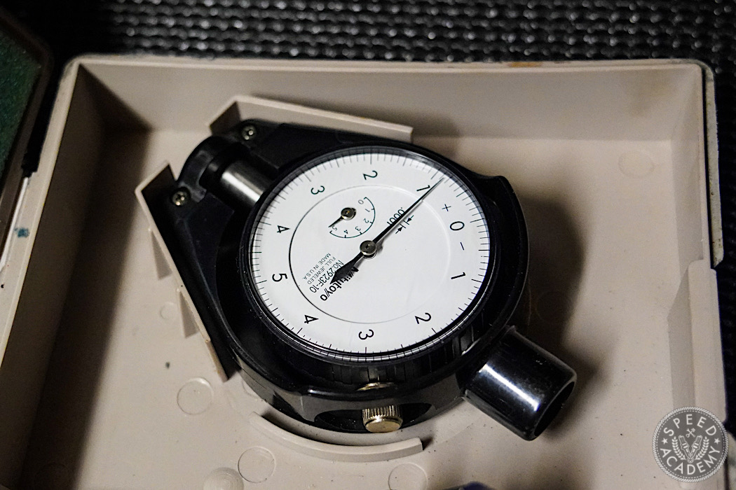
We will need some fairly simple tools to get this job done. There are some rather expensive options for these, such as those made by Mitutoyo and Fowler. If you can afford these new, or can find a clean example used, you absolutely have my blessing. I’ve personally had good luck with Chinese tools and I also have Mitutoyo examples, which I’ve used to verify the cheap alternatives and they are every bit as good.
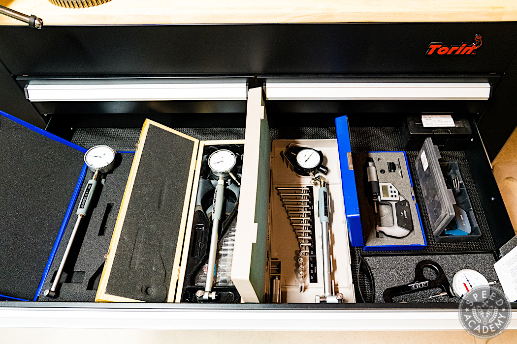
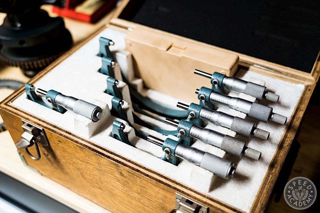
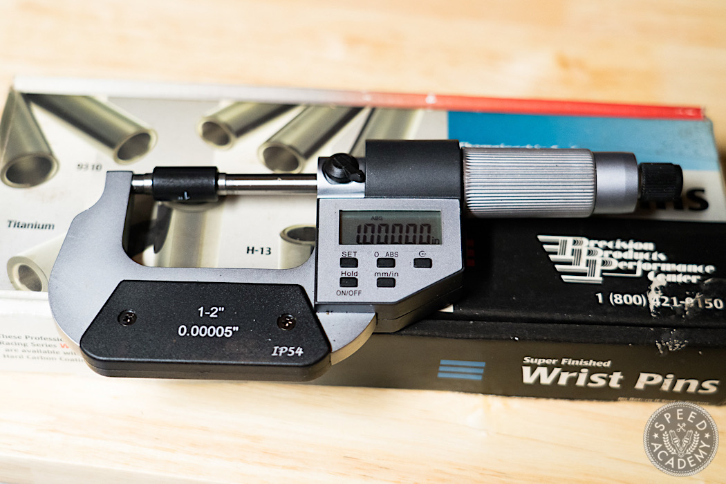
This will be the most important drawer for this project. It has my bore gauges, micrometers and an ARP stretch gauge. The reason for the variety is range. The micrometers typically cover 1”, so in this picture are my 0-1” and 1-2” micrometers. I have a full set of mechanical Mitutoyo micrometers as well, which I will need for the ~60mm crank journals, or maybe I will find a good deal in a nice 2-3” digital. The bore gauges also cover a fixed range and the smaller you go, the narrower the range becomes and they can add up quickly if you buy name-brand. For my purposes, I have a 0.7-1.5”, 1.4-2.4”, and a 2-4”.
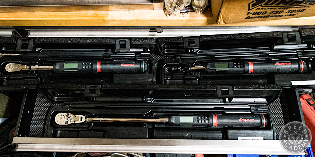
In addition to measuring things that are being assembled, the other critical tools are torque wrenches. I personally invested in Snap-On Techangle wrenches in ¼, ⅜ and ½” to cover everything from cam cap nuts to head studs. When we get around to using these, I will also discuss some important considerations in using them because most guys do it wrong (eg if your wrench beeps or clicks without the fastener moving, you have NO idea if the torque is correct or not). You don’t need anything this fancy but you will at least want to have a calibrated wrench. There are widely available services for doing this since all serious machine shops and mechanics will want to have their wrenches checked often. I’ve had my Mastercraft Maximum ½” wrenches tested and they are very good.
Let’s Begin
I will get into detailed measurements in the next instalment but let’s start with one to get an idea for what’s in store. The following procedure will be a common theme in different applications. The Carrillo spec sheet says that the wrist pin, also known as the “small end” of the rod is machined to 0.8672”.
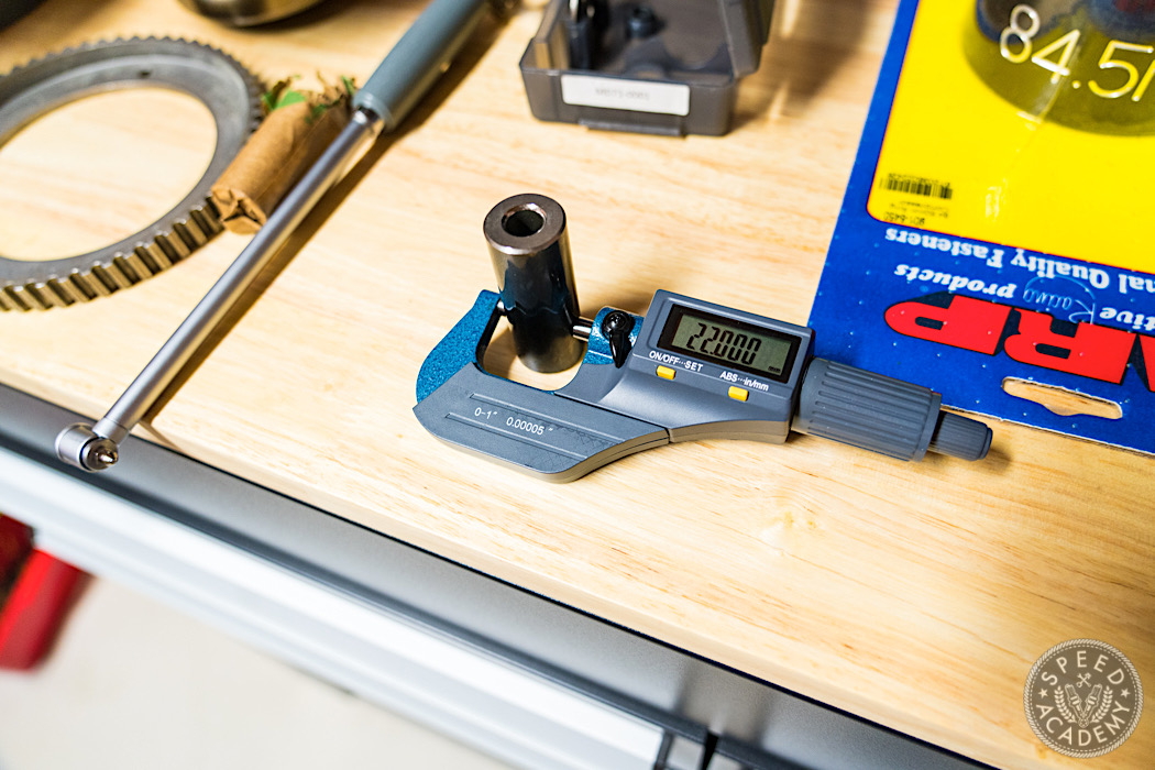
The wrist pin spec size for these motors is 22mm, and my super beefy coated pins are dead on. We measure the pin, or whatever the “male” part in question is with the micrometer, and once the measurement feels right, flip the little lock to fix the micrometer in place.
It’s a bit of a feel thing but it’s not hard to know when you hit it. I found it best to learn the feel of the mic with the reference block that is usually included. These are precisely machined for a range that fits the micrometer. They’re meant for calibrating the tool if it goes out of spec but when it’s fresh, you can also use it to learn the feel of a proper measurement. Fiddle with it gently until you get it to read what it should.

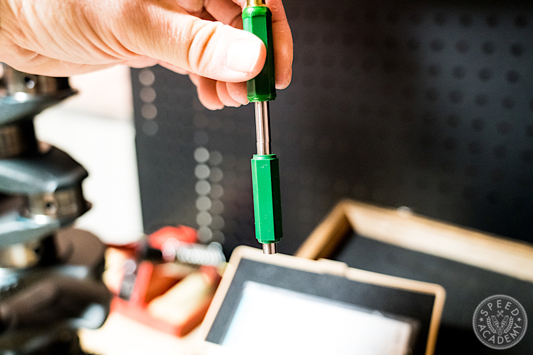
Things machined this precisely will vacuum seal themselves together and you can feel when you carefully wiggle the mic around, while tightening, when it takes a set and there is no more movement. It will feel like the two things just melted together.
In order to ensure you don’t apply too much force and crush the part, micrometers come with two knobs, one for fast and coarse adjustment, and the other has a ratchet, so that as you close in on the final figure, you turn this knob until it starts clicking. Like putting on your car’s ratcheting gas cap, you know it’s at the correct force.
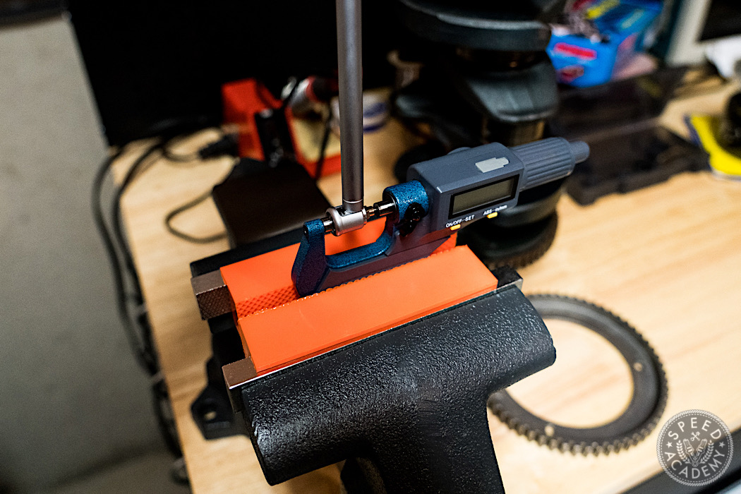
Now it’s time to set the bore gauge. Assemble it, picking the anvil that is the nearest size up from your target. Put the locked mic into a vice and put the bore gage measuring tip into the jaws of the mic.
Wiggle it around and watch the needle. There will be a point where the reading is the smallest – the needle will bottom out there, and then go back up. Rotate the gauge face ring so that 0 is at this point.
Your bore gauge is now zeroed. Now if we measure something, the measurement will be the difference from the 22mm wrist pin.
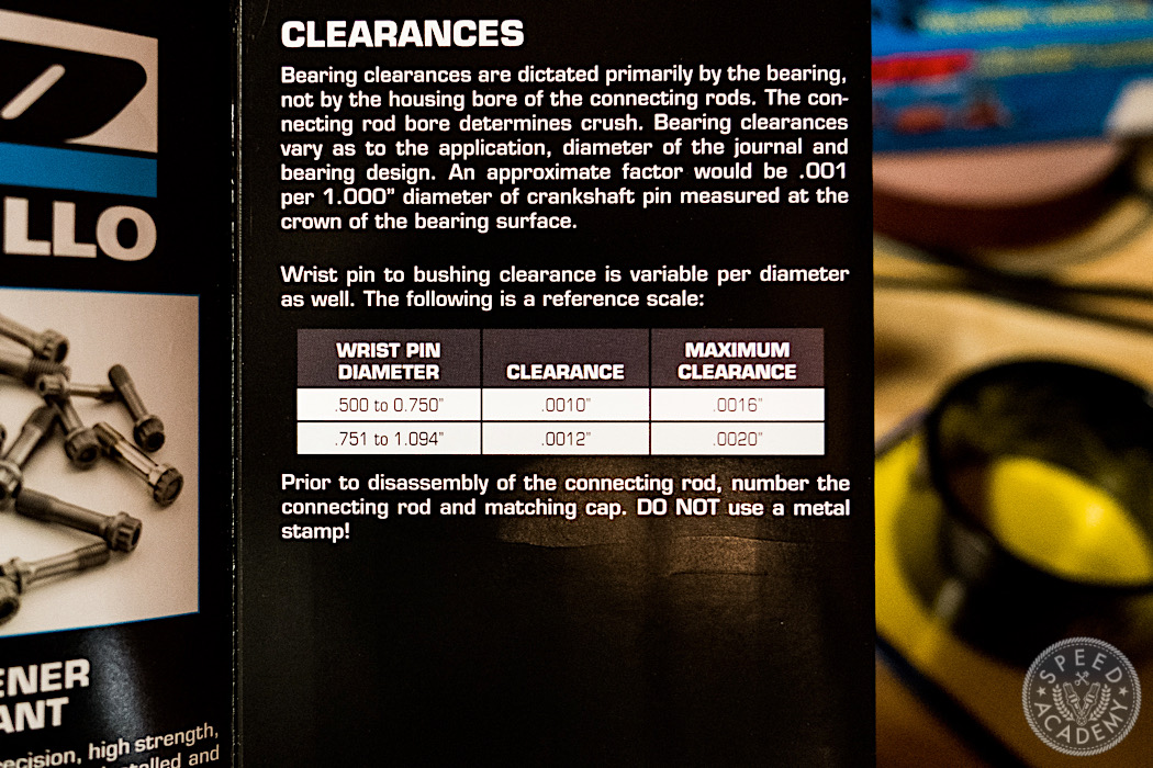
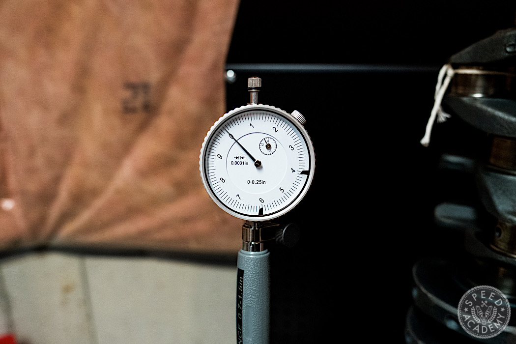
The Carrillo spec sheet says that for wristpins of my size (0.866), the clearance should be 0.0012”.
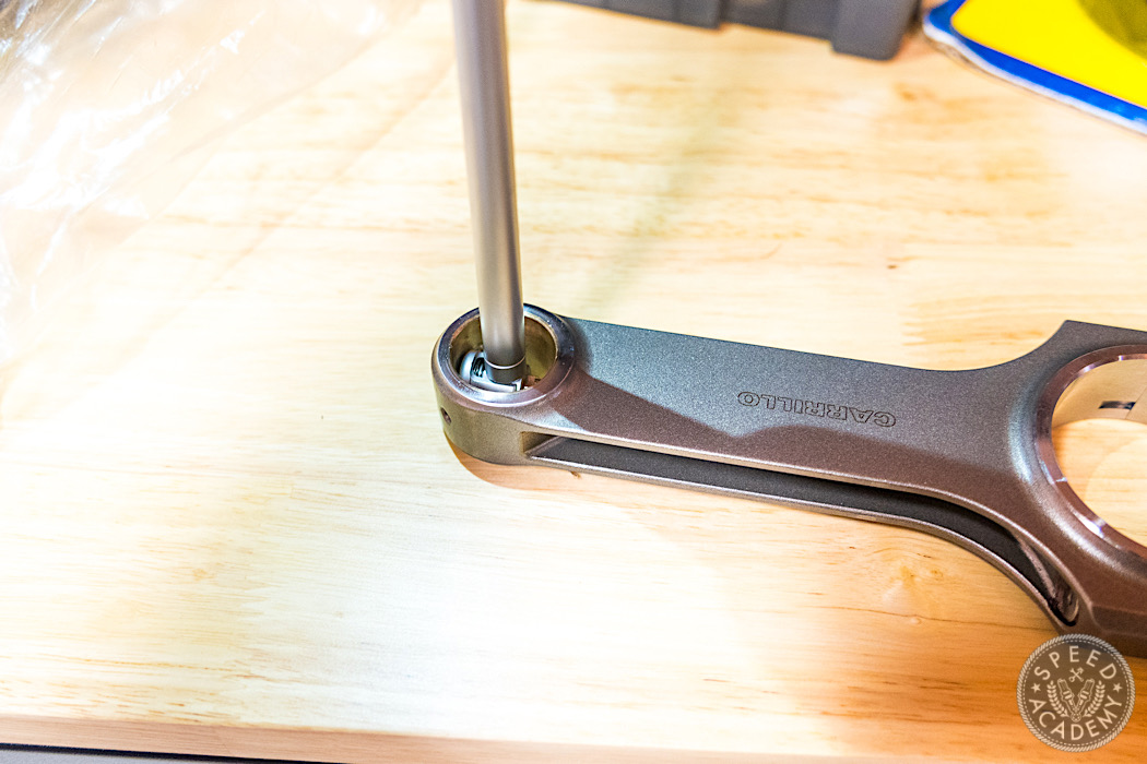
Again, insert the tip of the gauge into the wrist pin bore, and gently wiggle it around until the number bottoms out. Be gentle here, as the brass bushing will get marked. If you don’t reef on it, the light scratches won’t affect anything. In fact, unless you have an oil starvation problem, you can tell if your engine was properly assembled because you will see bore gauge marks on the bearing surfaces if you take it apart.
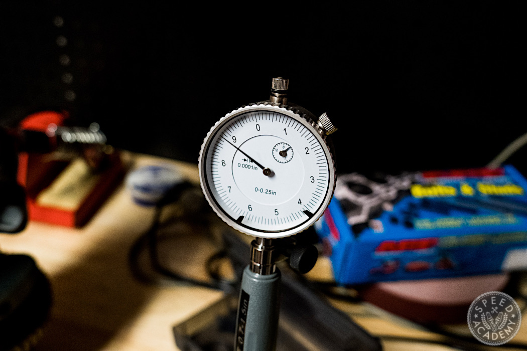
The gauge shows that the measurement is 0.0012” bigger than our zero, and that’s our clearance! This is an economy Chinese gauge so the reading is odd because it looks smaller – the dial indicator is generic, and normally they only measure one direction. These should really be +0.005 to the left of 0 and -0.005 to the right. My 2-4” bore gauge is a nice Mitutoyo, it has a proper dial face for bore gauges.
Anyway, the conclusion here is that Carrillo sure do build a fine rod!
Next time, it’s more of the same. The block will go in for machining and I will cover what you need to tell your machine shop, and what to check when you get it back. We need to measure the crankshaft journals, the engine block journal bores and the rod journal bores, so we can figure out what size bearing shells to get so we hit the clearances mentioned earlier. Then it’s time to put it all together.
Are you starting to wonder yet why you’ve been paying someone to do this for you, often incorrectly? To be continued…

Testing