If you’re a regular reader, you’ll recall JP’s Honda F20C-powered Datsun 510 from a series of stories and videos we did earlier this year. JP wasn’t happy with how the car was behaving in the corners, since it had a tendency to transition rapidly into oversteer (not quite as evil as full-on snap oversteer, but not too far off). And since his second-hand Stance coilovers were worn out, we decided we’d change out the shocks and springs and attempt to do some science when selecting spring rates in the hopes of hitting on a grippier and more confidence-inspiring setup.
When selecting spring rates for a track car we normally take a close look at what the fastest teams are running on the chassis we’re working with, plus we often consult with suspension setup experts who have a lot of experience with the specific car in question. With JP’s 510 that’s not as easy to do, though, not only because there just aren’t a lot of these left but also because he’s re-engineered the front suspension entirely and has also moved the rear lower shock mounting position as well. So the suspension geometry up front is completely different than a standard 510, and the rear is converted to a coilover setup from the factory spring on the rear semi-trailing arm.
Since we’re kind of in the dark with a unique creation like JP’s 510, we instead went back to basics and decided to do some maths. The M-word might scare some of you, but the truth is this process was really quite enjoyable and although we’re far from experts on the subject it was reassuring to find that our calculations coincided closely with the physical ‘suspension stroking’ method we cross-referenced it with. I’ll go into more detail on the stroking method later, but for a quick idea of what I’m talking about you can jump to 6:35 in the video above.
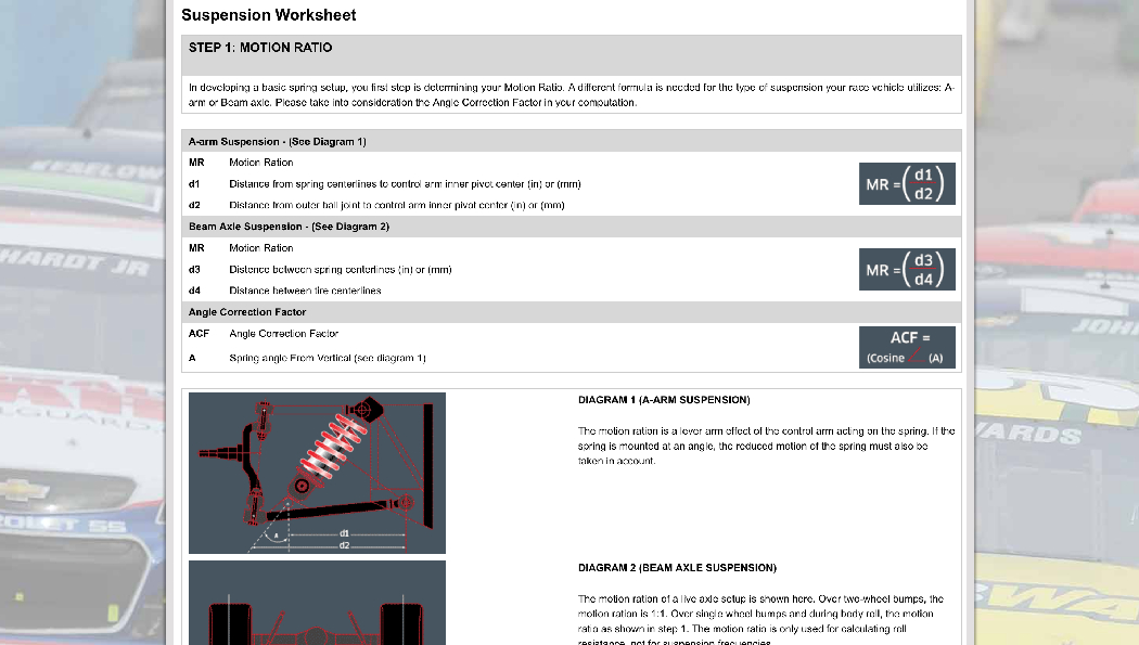
For those of you who want to do your own spring rate calculations, there are some good online resources for this including Eibach’s suspension worksheet, which does an excellent job of explaining the different measurements required and how these allow you to calculate key variables including Motion Ratio (the mechanical advantage or lever ratio that the wheel has over the spring in compressing it) and Wheel Rate (the effective spring rate at the wheel, due to the leverage advantage the wheel has with respect to the spring on the control arm).
Before we delve into the measurements required to calculate Motion Ratio and Wheel Rate on JP’s 510 (or any car), first let’s cover the subject of Suspension Frequency (sometimes called Ride Frequency). Suspension Frequency, measured in cycles per minute (cpm) and expressed in Hertz (Hz), is defined as the undamped natural frequency of the body in ride. Imagine a car with no shock absorbers and how the suspension would oscillate on its springs as you drive it down the road. A car with stiffer springs will oscillate more rapidly (higher Hz) and have a harsher ride, while a car with softer springs will oscillate more slowly (lower Hz) but have a more comfortable ride. For you math nerds, here’s the equation for Suspension Frequency, where WR is Wheel Rate and Sprung Weight refers to the parts of the car that are supported by the springs:

Although it’s possible to calculate the Suspension Frequency, as you can see we need to know the Wheel Rate to do this and to calculate Wheel Rate we need to know the spring rates. It’s kind of a chicken or the egg conundrum, so we prefer to select a Suspension Frequency rather than calculate one. According to OptimumG, a vehicle dynamics consultant group that trains race engineers and offers sophisticated software packages that help race teams dial in their racecars, these are good ballpark Suspension Frequency ranges to work from:
- 0.5 – 1.5 Hz for passenger cars
- 1.5 – 2.0 Hz for sedan racecars and moderate downforce formula cars
- 3.0 – 5.0+ Hz for high downforce racecars
It’s interesting to note that more often than not passenger cars are setup with higher rear suspension frequency, since this helps bumps in the road to be absorbed “in synch” by the front and rear suspension and has the effect of smoothing out the ride quality. However, according to OptimumG, “A higher front ride frequency in a racecar allows faster transient response at corner entry, less ride height variation on the front (the aerodynamics are usually more pitch sensitive on the front of the car) and allows for better rear wheel traction (for rear wheel drive cars) on corner exit. The ride frequency split should be chosen based on which is more important on the car you are racing, the track surface, the speed, pitch sensitivity, etc.”
Since a lower suspension frequency produces a softer suspension and more mechanical grip (but also slower transient response or a delay in the suspension’s reaction to sudden changes in direction), there is some tradeoff involved here. Furthermore, in my experience too high a suspension frequency will produce a very unforgiving car when driven at the limit and one that may struggle to put heat into its tires. So suspension frequency is definitely not a case of “more is better”. In fact, at the tight and bumpy Toronto Motorsports Park where we do a lot of our testing, a softer setup that generates more mechanical grip often delivers better lap times. That being said, high suspension frequencies do create less suspension travel for a given track, allowing lower ride heights, lower center of gravity, and improved aerodynamics, so at a smooth and fast track like CTMP (Mosport), higher frequencies work very well.
Rather than marrying ourselves to a specific Suspension Frequency at this point, we’ll simply use it as our “fudge” factor once we get to the point that we’re calculating Spring Rate. If we find the calculated Spring Rate with a 2.0Hz front and 1.8Hz rear Suspension Frequency yields spring rates that we feel are a bit too high or low, we’ll adjust SF to coincide with our years of experience choosing and testing spring rates on a wide range of track cars and race cars. We will likely settle on a lower SF for the rear of the 510 than the front, since we wanted to soften the rear setup to help dial out its tendency to oversteer. Now it was time to get on with the fun of measuring the front and rear suspensions so that we could calculate the car’s front and rear Motion Ratios and Wheels Rates, which would allow us to start calculating spring rates.

Source: http://cdn.rodauthority.com/image/2012/09/Motionratio-front.jpg
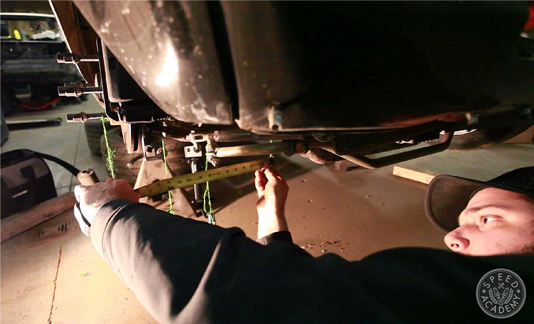
As you can see from the above image, Motion Ratio is simply the difference between Dimension A and Dimension B, which we measured on JP’s 510 with the suspension jacked into the position it would be if it were resting on the ground (as you’ll see in the video, the car was on jack stands when we were working on it).
We measured the front suspension, which is a MacPherson strut design and thus going to be close to 1:1. Based on JP’s highly technical plumb bob method of marking our measuring points (lol), we ended up with a Motion Ratio of 0.975.



Having read an awful lot of opinions on the subject of spring angle correction factor, the consensus of opinion is that it should also be squared in the calculation, just like the motion ratio is. Any thoughts?
When you think about it, you have already accounted for the spring angle on the front suspension with your empirical measurements because you measured the actual displacement of the strut in situ, ie at its installed angle. This measurement takes full account of the impact of both lever arm ratios and installed spring angle, on the motion ratio. If you wanted to apply the spring angle correction factor separately you should have measured only purely vertical displacement of ball joint on the suspension arm. This would have given only the lever arm motion ratio.