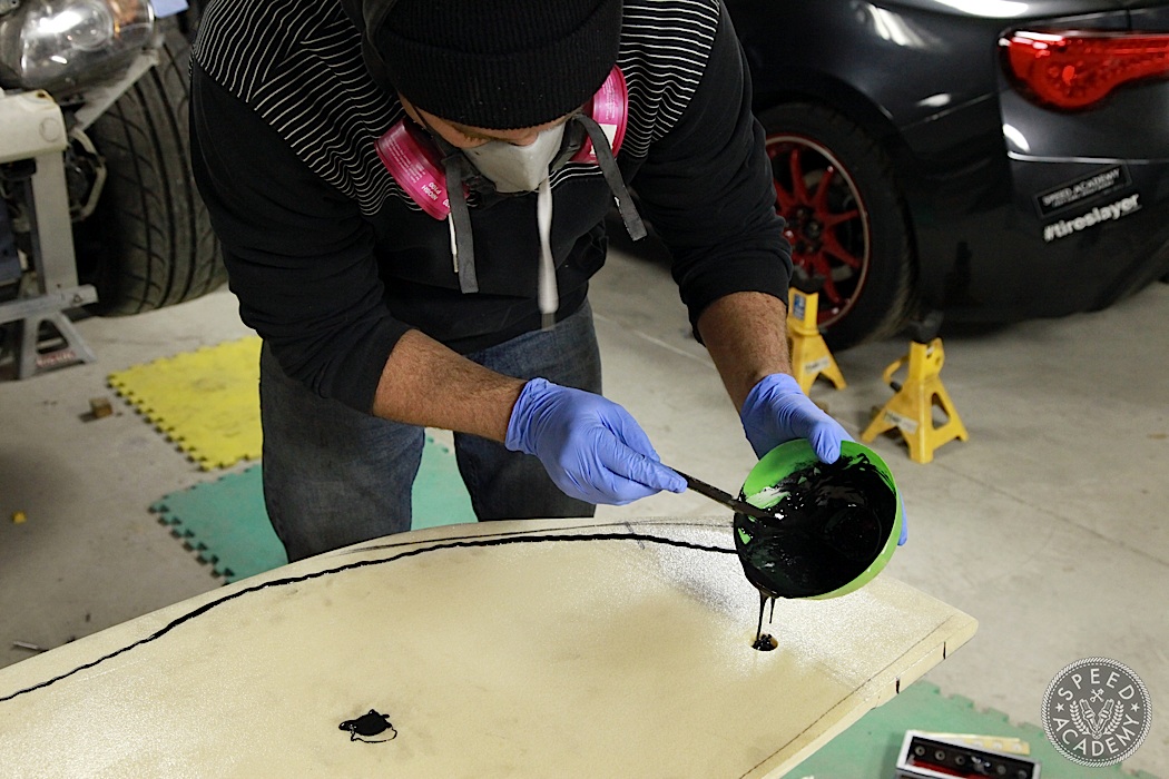
In Part 1 of our custom splitter build with Kevin from C3 Composites, we showed you how we built a template and then cut, prepped and temporarily mounted the high density 3/4” foam core that would be at the heart of this carbon fiber wrapped downforce making device. We also showed you how the main mounting system would work on the old ASS2000, a project presented by Turn14 Distribution, and then in Part 2 we showed you how Kevin wrapped the core in 3 layers of carbon fiber fabric treated with a resin hardener to give it strength, then sanded, treated again with resin, sanded again and finally clearcoated.
It was, as they say in the pant business, a buttload of work, but the finished splitter is a genuine work of art thanks to Kevin and it will allow us to run an aggressive rear wing on the S2000 and maintain excellent front/rear aerodynamic balance. Without a proper splitter like this, the rear downforce from the APR Performance GTC-300 wing we’ve opted for would literally lift the front end, causing understeer while simultaneously generating more rear grip (which from the driver’s seat will feel like even more understeer since grip has been biased to the rear).
What we haven’t shown you fully (though we did show you a good portion of it in our ‘Completing The Aero Package’ story) is how we finalized the mounting system for the splitter, nor have we shown you how we built the carbon fiber front bumper diversion plates, which connect to the back edge of the splitter in the wheel wells and divert air over/around the front tires, which stick out past the bumper enough to cause significant turbulence and airflow disruption.
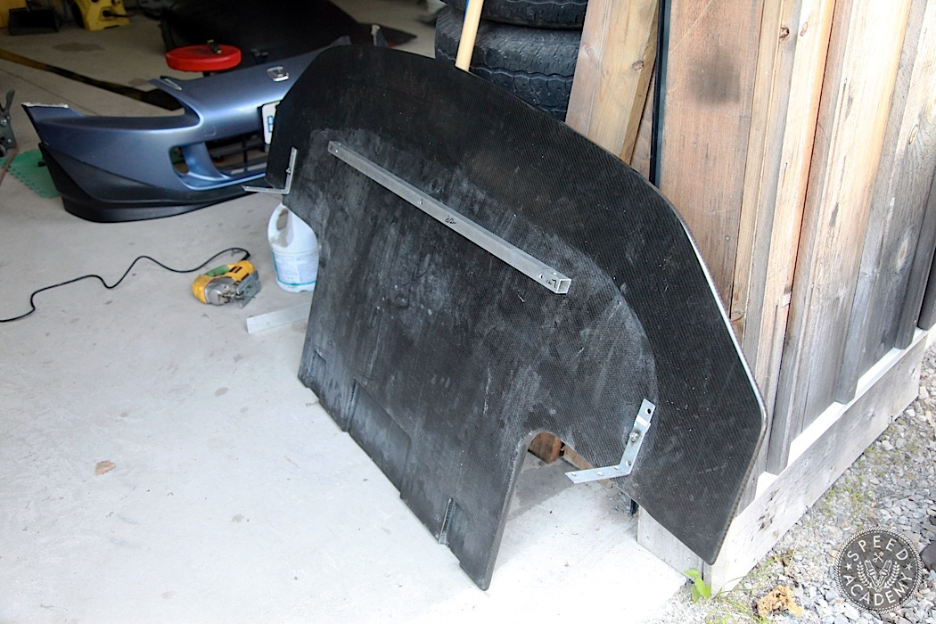
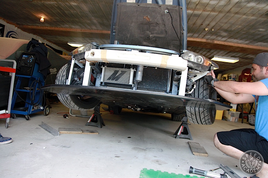
Alright, lets get down to business. For starters, Kevin mounted the aluminum square bar to the top side of the splitter in the locations we had determined and reinforced with a hard, non-compressible resin core back during Part 1 of the build. As you can see, we’ve also installed L brackets with a captive nut welded on the top side. More on these outer mounting points in a bit.

During mockup we used long thru-bolts with a nylon lock nut on the backside of the central cross bar, but because we want to be able to remove the splitter easily from the underside, for final assembly we installed rivnuts (which install like a rivet but have a threaded hole in the middle) in the aluminum bar so that we could use a tapered head bolt to fasten the splitter from the bottom side.
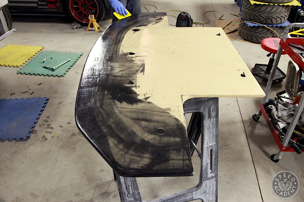
For the two rearmost mounting points, which you can see above with the two black resin filled holes along the back edge of the splitter, we welded nuts into a couple of existing holes in the front subframe and used OE bolts from our random bin of leftovers (why do we always have leftover bolts?) to fasten it in place.
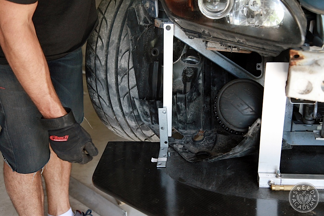
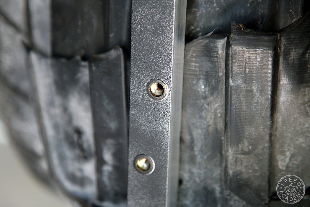
We added the outermost mounting points as a last-minute “lets make it stronger” decision, but we didn’t make the actual mounts at the time. We basically just eyeballed where we thought these holes should be, so once we had the completed splitter back from Kevin we set about making these outer mounts. Again we decided to use aluminum square bar, this time bolting it to the chassis below each headlight and to the splitter via highly technical L brackets from Home Depot.
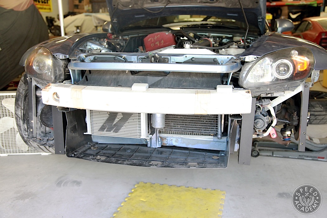
We did, however, “tune” these brackets by welding on captive nuts so the bolt up through the bottom side of the splitter can be removed without needing access to the top side, and we used our fancy rivnuts in the square tubes to create threaded mounting holes for the vertical portion of the L bracket to fasten to. Plus we painted them black, mainly because of Peter’s OCD but also because the central vertical mounting bars can be seen through the brake duct openings in the bumper cover.
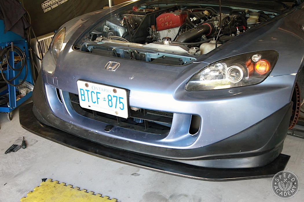
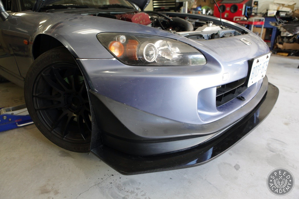
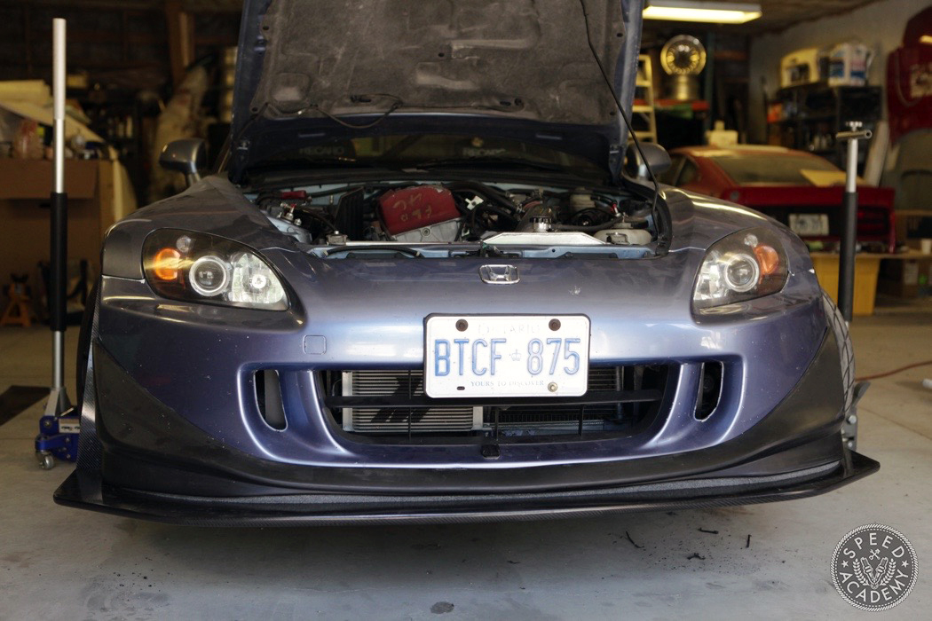
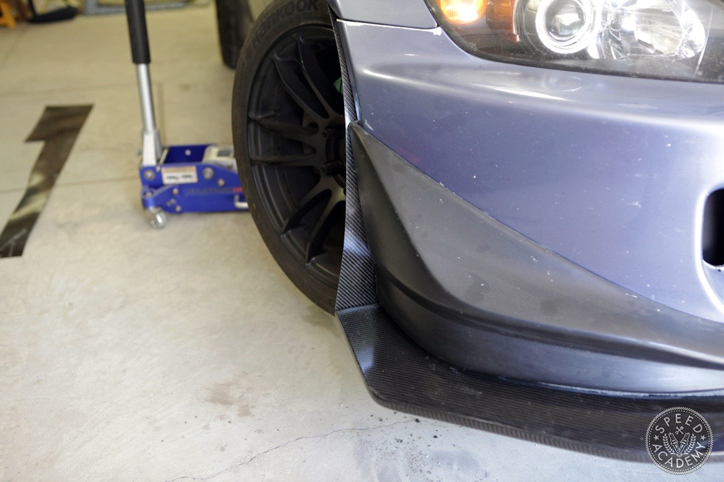
With all the mounting points dealt with, we could finally mount the splitter to the chassis and install the front bumper. As you can see, the splitter sticks out a couple inches past the outer edge of the front lip, and this is by design. We always intended to add a air diversion plate that sticks out from the bumper to divert air over/around the front tires, as we’ve already shown you earlier.
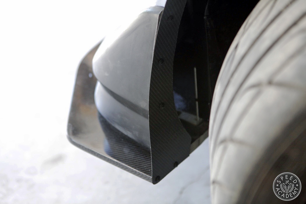
Kevin had some 2-layer carbon sheet material available for this job. In this thickness and without a foam core, the 2-layer layup is quite strong but still flexible enough to be fastened to the inside of the bumper cover along this curved surface. We simply cut it to shape with tin snips, as you’ll see in the Bonus Video at the bottom of the post which covers some of the splitter installation, and then fastened it to the bumper cover using self-taping screws (we drilled small pilot holes first).
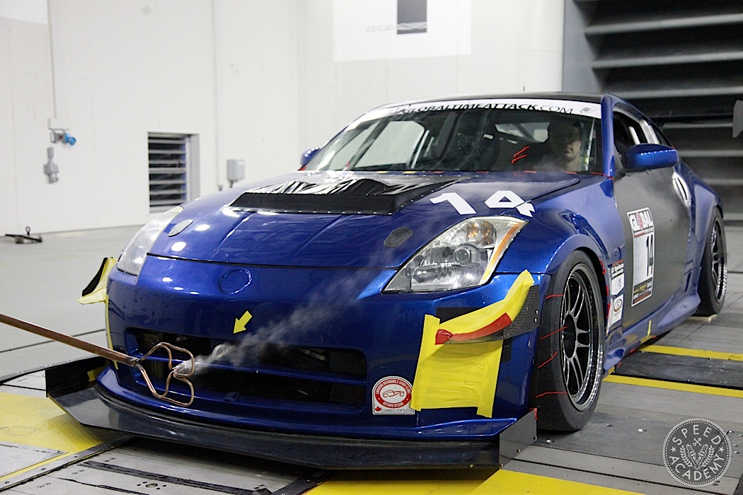
Eventually we’d like to add splitter endplates and maybe front bumper canards too, similar to Sasha’s 350Z during the wind tunnel testing story we did with him a few months ago. But first we want to go testing with the aero package on the ASS2000 as it is, to evaluate the overall balance of the car.
In the meantime, check out our Bonus Episode on Project ASS2000 (it’s a bonus because we didn’t plan to shoot a video on this stuff, but decided we’d throw something together as a way of sharing the fact that it’s often the small details that up to faster lap times). And if you missed Part 1 and Part 2 of our splitter build with Kevin from C3 Composites, you’ll find the links below, because we like to make things easy.
Was the foam left in the carbon or was that used for a mold or template?
looks like its glassed over and stays in the core