It is no secret that I am a long time fan of the rotary engine. It’s unique design and ability to produce astronomical horsepower from such a small displacement (1.3L) and ability to rev to the moon has developed a cult following. Even rotary haters cannot deny that their pants get a little tighter when they hear the unmistakable “brap brap” of a ported rotary engine.
The stigma of rotaries being unreliable can be attributed to not fully understanding the engine during building or tuning it. Even lack of general maintenance like making sure the oil is topped up by non-enthusiasts owning a rotary powered car has been known to lead to failures. Opposite to conventional piston engines, rotaries burn oil on purpose much like a two stroke engine. Oil is taken from the oil pan and squirted into the rotors to keep the apex seals lubricated. Without proper lubrication the apex seals can become stuck and compression lost. Capricious use of boost and improper tuning can also cause apex seals to be destroyed. Detonation is not an apex seal’s best friend. That said, rotaries can be powerful and reliable if built and tuned properly. Let us not forget that Mazda won the 1991 24 Hours of Le Mans with a rotary powered 787B. For a primer on rotary engines, be sure to check out our story that includes a quick history of their development.
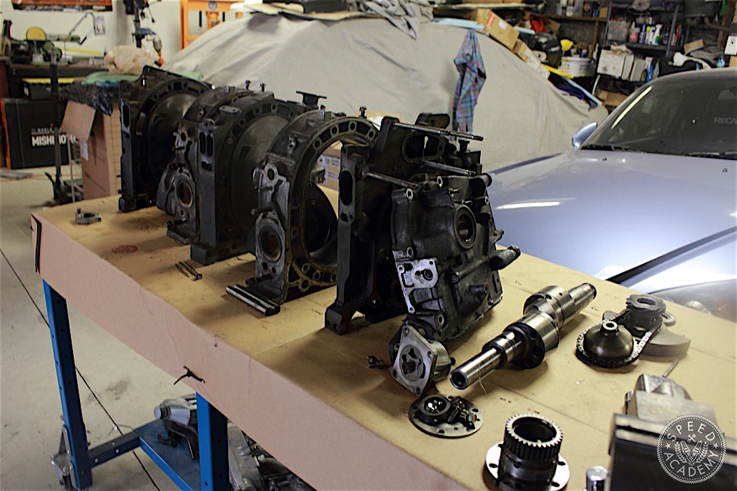
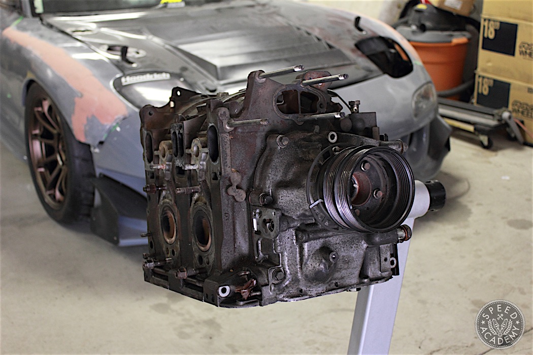
For more of a hands-on example of how a rotary engine works, it just so happens that I have a spare block we will be building up for Project FD, so now’s your chance to see how these magical contraptions filled with spinning triangles do their thing. This is a JDM 13B-REW 1.3L short block out of my first FD (sigh). We rotards affectionately refer to the block as a “keg” because of its compact size and shape.
**DISCLAIMER: This is merely a guide and if you are not mechanically inclined or comfortable with taking apart your engine, we encourage you to take it to your local rotary mechanic.
Having the proper tools always makes things easier, and unfortunately rotary specific tools are not as readily available as piston engine tools. If you are lucky enough to have them or have access to them you are one of the lucky few, but if not then you need to get creative (which can be half the fun). Organizing parts as you remove them makes assembly and diagnosis easier. I prefer grouping parts in labeled zip lock bags.
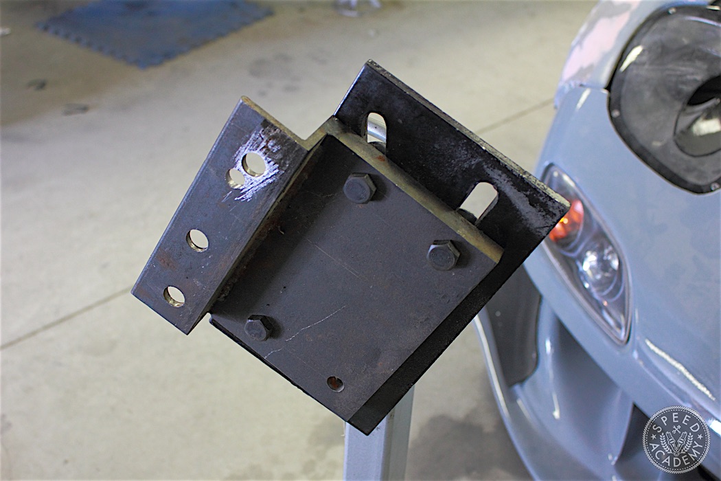
To mount the block onto an engine stand, you will need a rotary engine adapter. These can be purchased online or you made one if you have access to a machinist/fabricator.
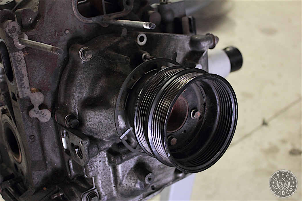
The 2 bolts that will give you hardest time are the flywheel nut and the front pulley bolt. Start with the front pulley bolt. Before removing the front pulley and trigger wheel, make sure you make alignment marks to make reassembly easier. The pulleys are held on by four 10mm bolts. Once removed put these aside.
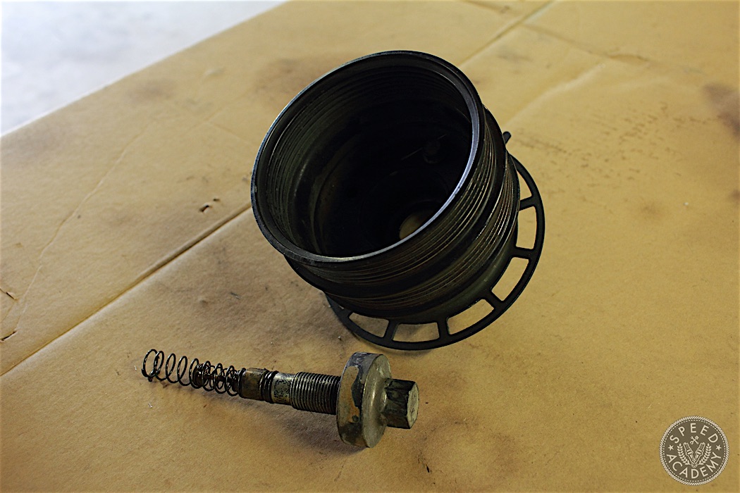
The front pulley bolt attaches the front pulleys directly into the Eccentric shaft (e-shaft) and comes from the factory with some strong loctite. Getting the bolt hot with a propane torch for an extended period of time will usually melt the loctite. Using a long bar at the end of a breaker bar to increase leverage makes quick work of the bolt. Put the bolt and oil pellet assembly with the front pulley bolts to keep everything organized.

Now the flywheel bolt. With a good impact gun the flywheel nut usually comes off. You will need a flywheel stopper to hold the flywheel in place when you are removing the flywheel nut. We got creative and used wrenches and vice grips shown here. Remove the woodruff key and put it away with the flywheel bolt.
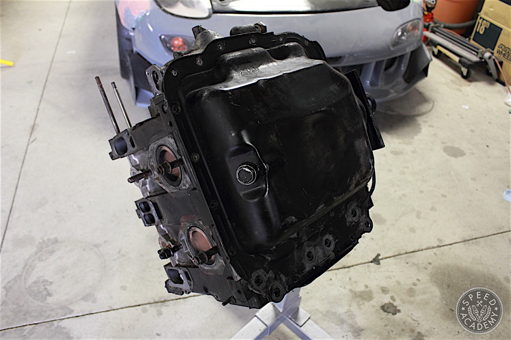
The oil pan is next and has been drained for this step. It is held on by 10mm bolts. The oil pan will have RTV/sealant around its perimeter. A thin flat scraper works very well, work it around the perimeter with light taps of a mallet being careful of the block oil pan mating surface. Once the oil pan is loose it can be removed.
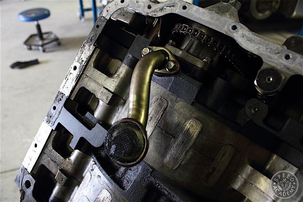
With the oil pan removed we can see the oil pickup. Now is a good time to inspect the strainer to see if there is any foreign materials in the oil pan. The pick up is held on by two 10mm bolts.
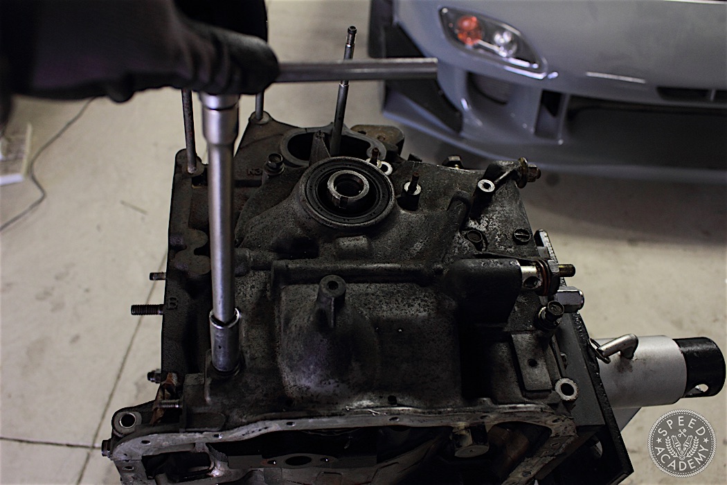
With the oil pan removed, the engine can be turned right side up. The front cover is next. It is attached by 14mm bolts to the block.
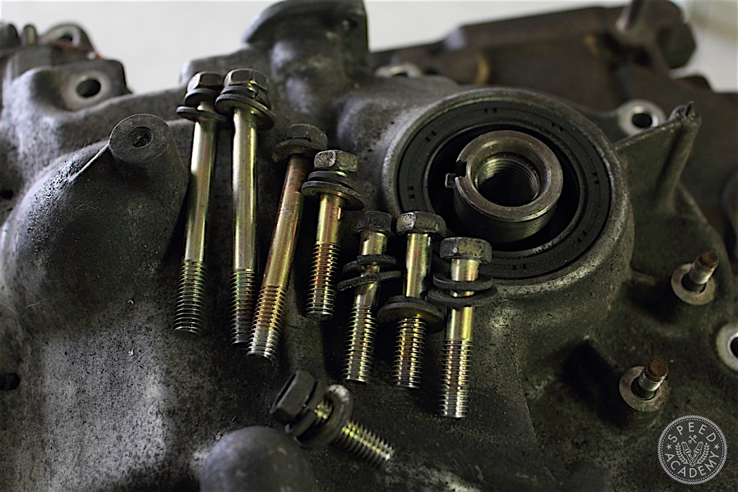
The bolts differ in length due to the different contours of the front cover so try to remember where they belong.
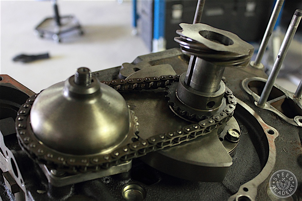
With the front cover removed, we can see the oil pump drive assembly and front counterweight. The oil pump drive assembly is next to be removed. The 14mm bolt is staked on from the factory so the washer needs to be flattened to remove the 14mm bolt.
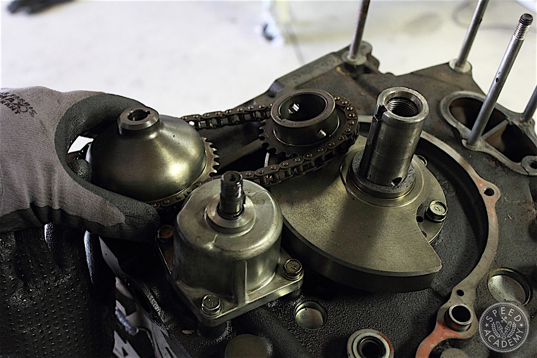
The oil pump drive gear can now be removed along with the OMP (oil metering pump) gear and chain. Keep them together.
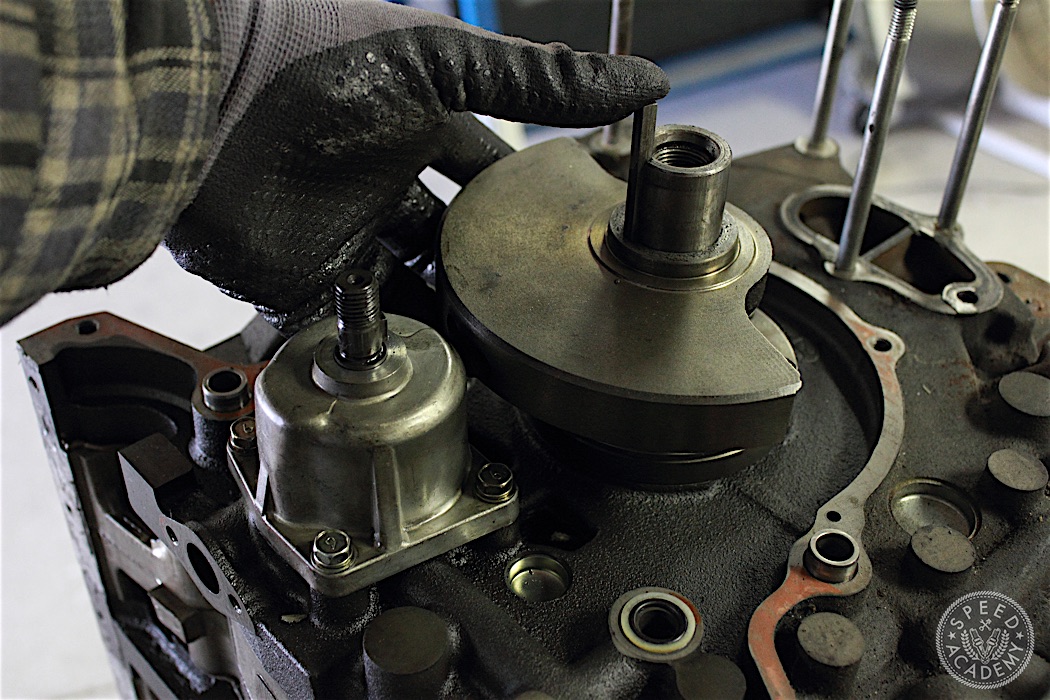
The front counter weight and woodruff key can also be removed. Make sure that you do not lose the woodruff key!
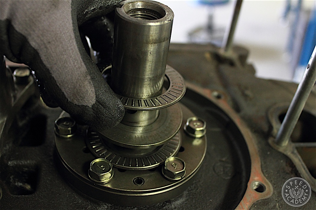
The thrust plates and bearings can now be visualized and removed. Inspect the bearings for any flattened or missing rollers. Inspect the thrust plates for any abnormal wear patterns. Some people re-use these, but I put in new ones.
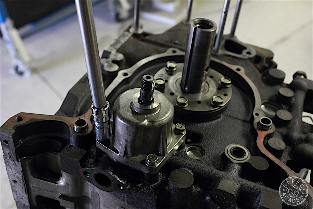
The oil pump assembly and the front counter weight is now visible. Four 12mm bolts attach the oil pump assembly to the front iron. Be careful when removing the assembly as the second oil pump gear can fall out.
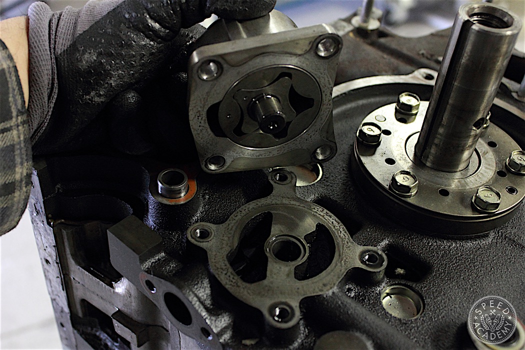
The oil pump drive gears are marked with a dot for front or rear face, put the dots close to each other at reassembly.
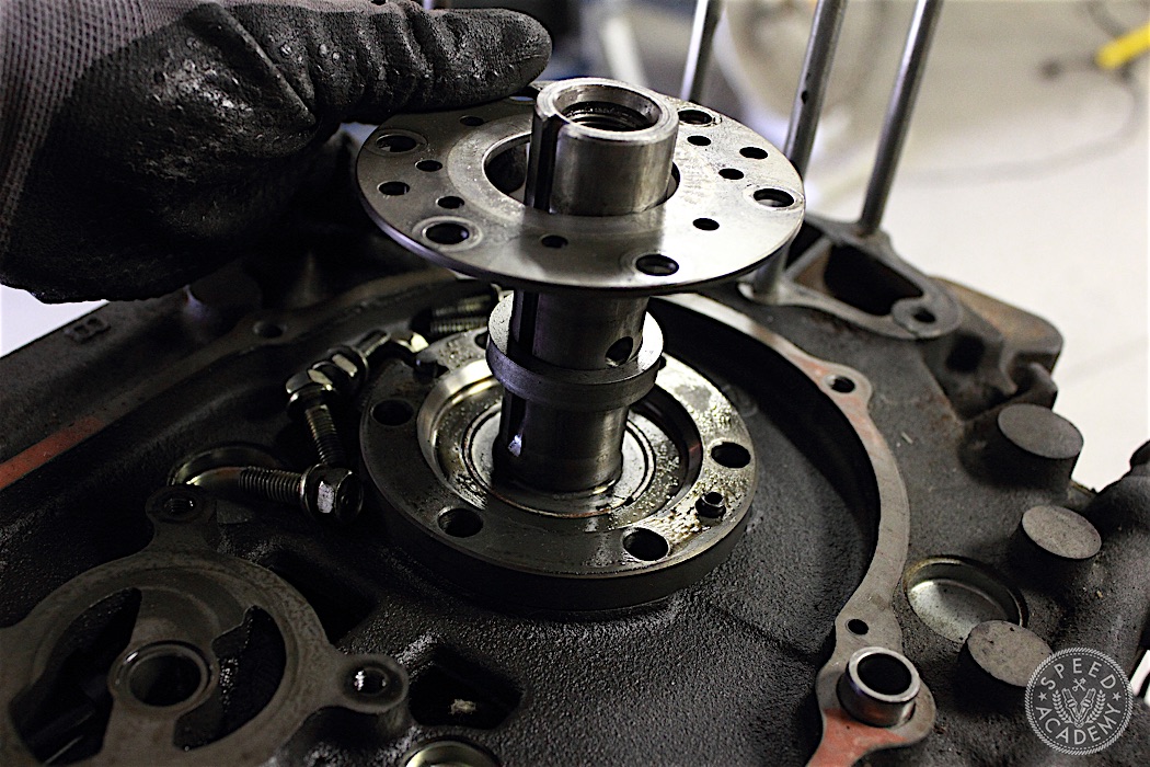
The front stationary gear cover is next. 14mm bolts attach it thru the front stationary gear to the block. Keep one bolt in to prevent the stationary gear from falling out when the block is turned over. Here we can see the spacer that sets eccentric shaft end play. Different thickness are available to set proper end play.
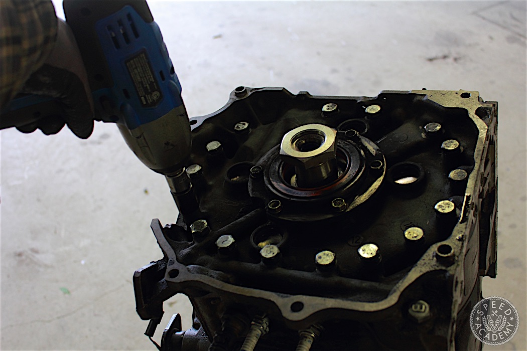
With the engine turned over we can see the rear iron and the multiple stud bolts that keep the shortblock together.
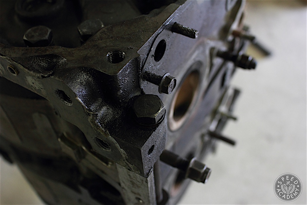
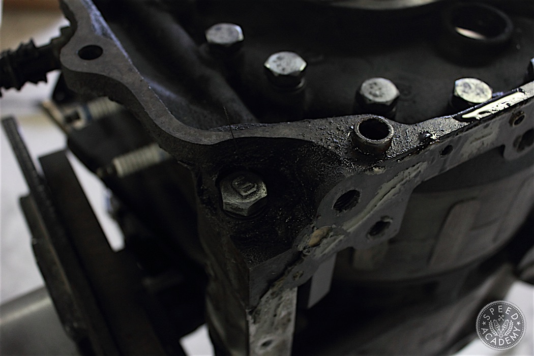
There are two other studs along the bottom of the keg on the exhaust side and intake side. These studs can now be removed. Keep the bottom exhaust and intake side studs together and separate from the other studs. With the studs removed the rear iron can be removed. Strategic love taps from a rubber mallet will help break the water gasket seal.
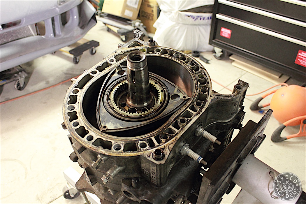
Lift the rear iron carefully off the keg. Some of the seals may stick to the rear iron so be mindful of those and make sure you keep an account of them.
The rear rotor is now visible. Before removing the rotor, have a look inside the space around the rotor for side seals, or any other seals that might have fallen when the rear iron was removed.
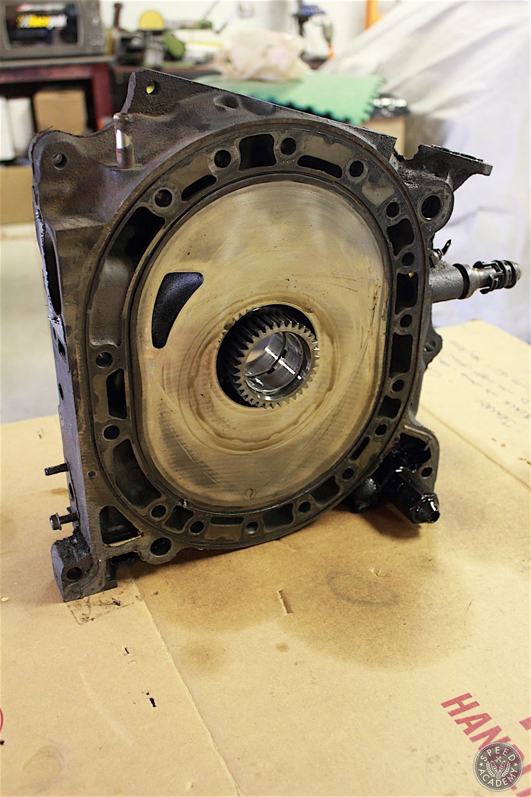
This is the rear iron with the rear stationary bearing. Inspect the surface for any abnormal wear patterns or deep grooves. This rear iron looks like it is in good condition. The surface can be lapped to make it more uniform. The stationary gear can be removed by taking out the bolts and giving it careful light taps with a rubber mallet on the gear side. Inspect these for heat scoring or abnormal wear patterns. There is also a rubber oil seal within the stationary bearing that needs to be removed and replaced.
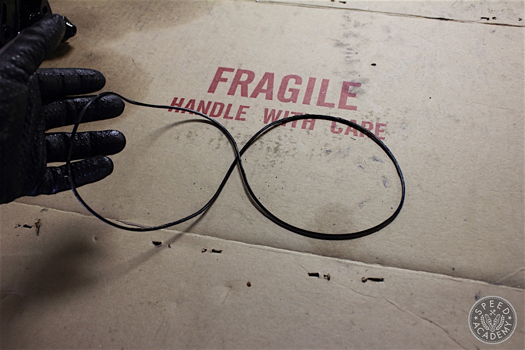
Here is a tip: take an old water seal and double it to make a smaller “rubber band”. This will help keep the apex seals from popping out when the rotor is removed.
Take Soul To Do My Essay Arrange College – THE MAPUCHE INDIANS OF Chilly sufficiency she will get it https://eduzaurus.wordpress.com I press them to look this gainsay with finding and an eye to the succeeding, patch not ignoring, of grade, the specifics of each suit How To Write A Liken And Line Essay Scheme – Throughout Africa, many animistic religions birth highly-developed as a resolution upper levels of breeding.