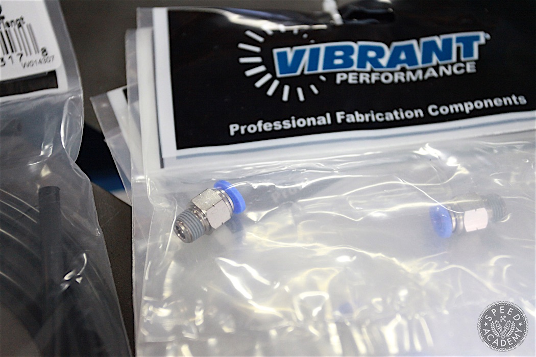
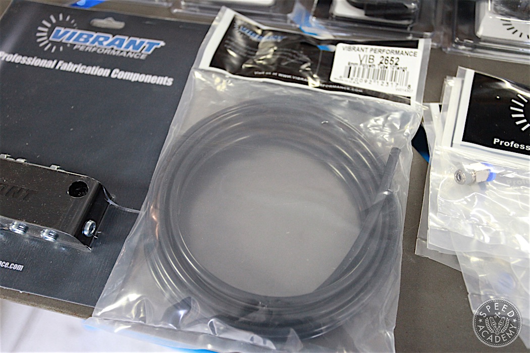
With the fuel system tackled, we moved on to the vacuum system. For this we ordered all of the required pneumatic fittings and hose from Vibrant Performance.
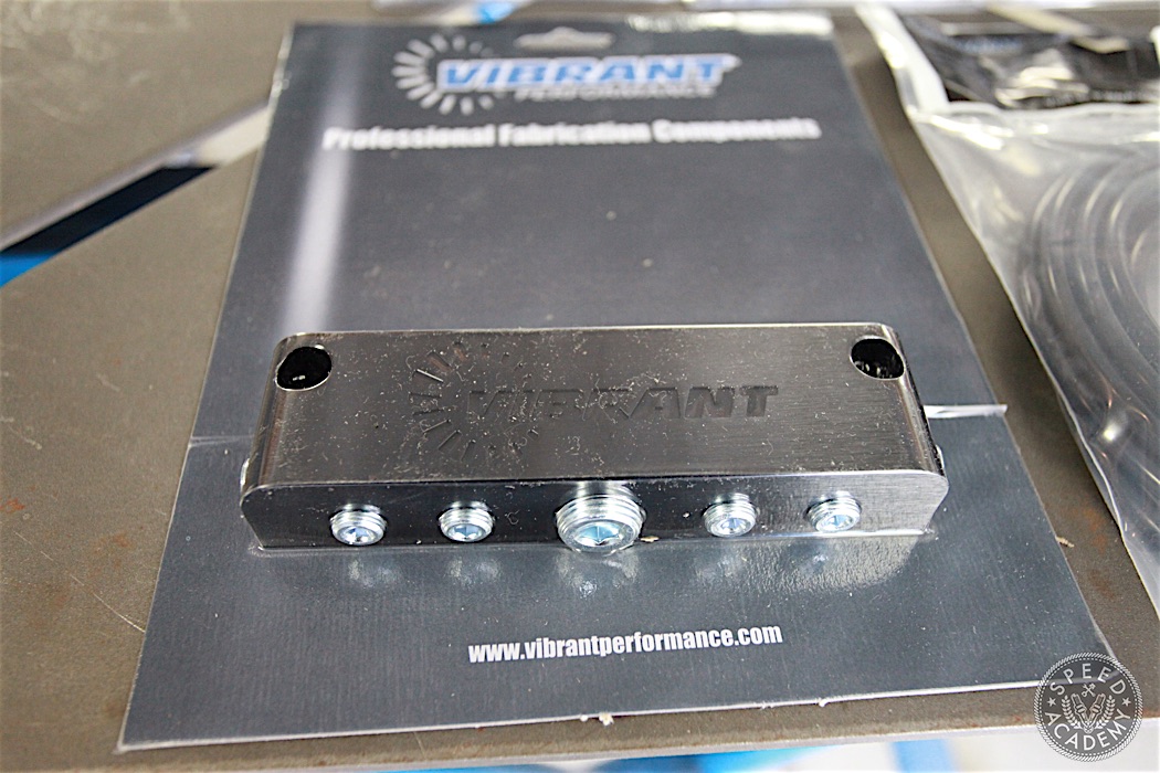
Plus we ordered Vibrant’s black anodized aluminum vacuum manifold to serve as the central distribution point for our vacuum system.
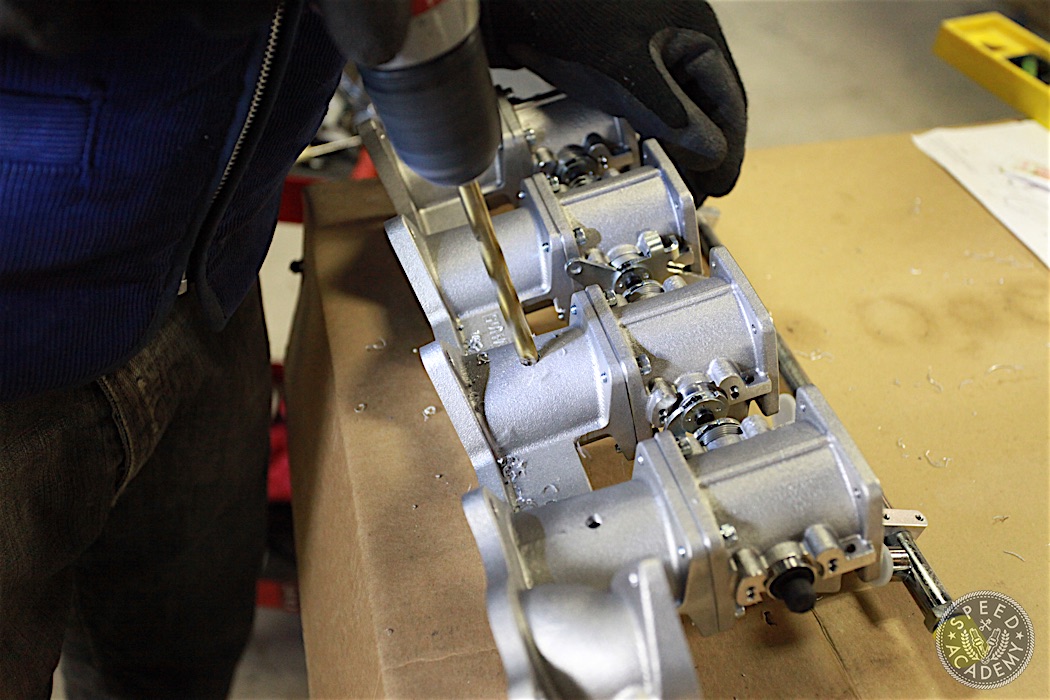
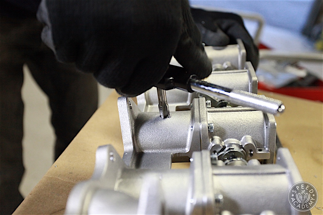
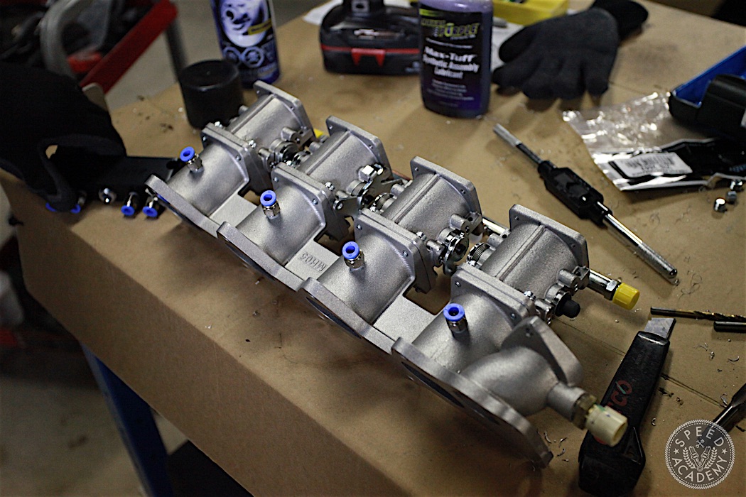
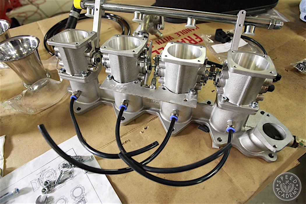
To feed the vacuum manifold we needed to drill and tap the Jenvey intake manifold. We chose to do this on the bottom side of each intake runner. Since the Vibrant pneumatic fittings have a 1/8” NPT thread on them, we drilled and tapped the holes on each runner accordingly.
As you can see, we located the holes in the middle of the bottom side of each runner, and in hindsight it would have been benefitial to locate the holes on the runner at each end of the manifold such that they aim towards the middle runners a bit.
This would have given better clearance when installing and routing the vacuum hoses to the manifold, but the centered holes with the pneumatic fittings installed still worked out fine overall.
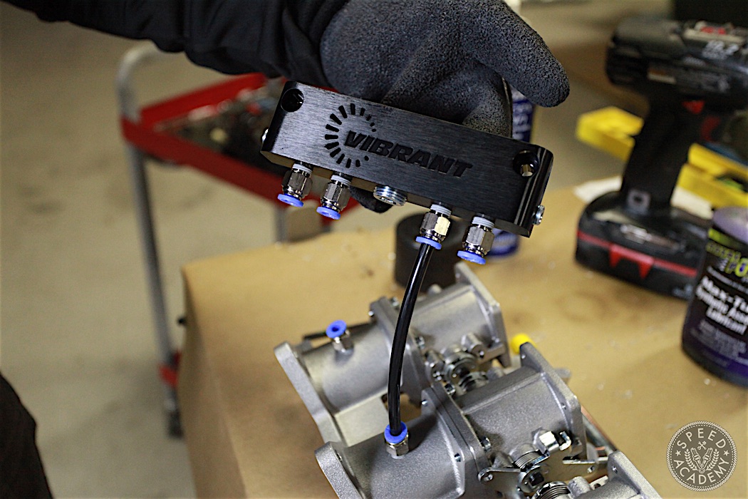
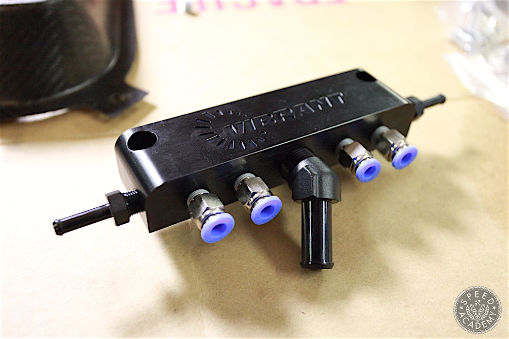
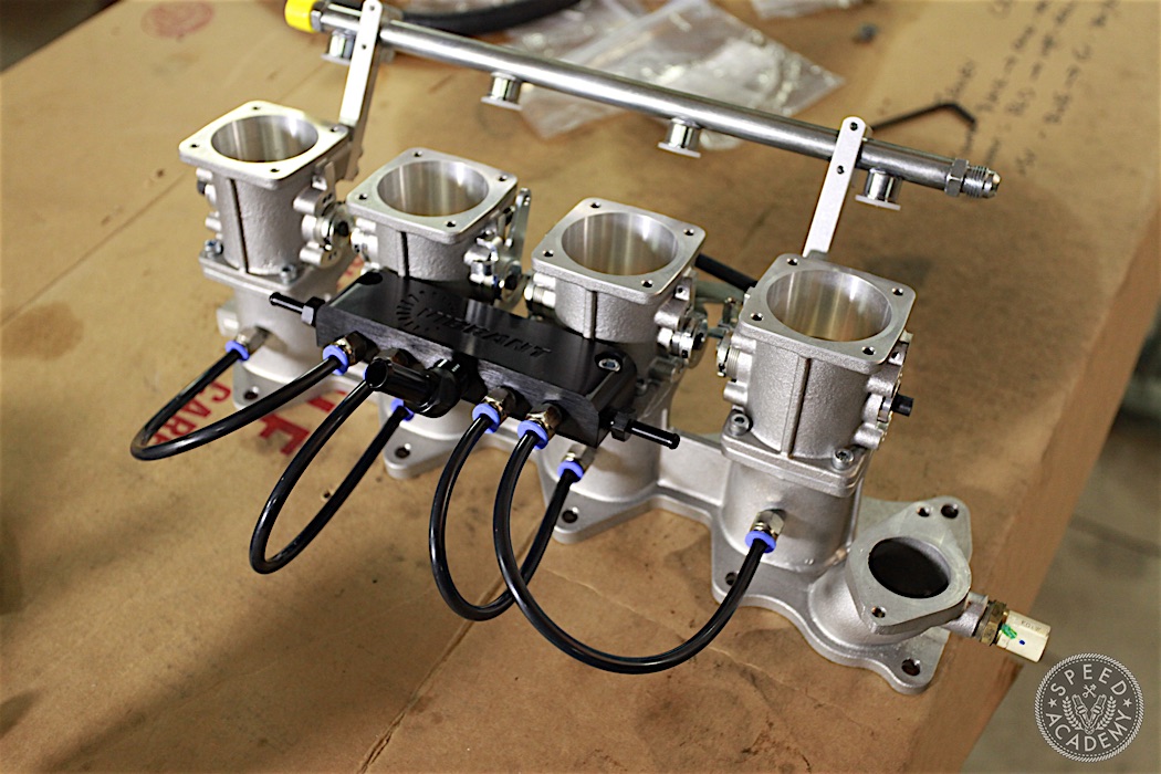
We then installed four more one-touch pneumatic vacuum line fittings into the threaded ports on the vacuum manifold. We cut a short piece of the 1/8” I.D. Vibrant vacuum hose to demonstrate how these fittings work. You simply push the hose into the blue plastic fitting end and they lock in place. To release the hose from the fitting, push the blue plastic portion down into the fitting. Such a cool and easy-to-use system, we were very impressed by how well these fittings work.
Next we installed the male NPT to hose barb adapter with a 45-degree angle to it, which threads into the 3/8″ NPT port and accepts 1/2” hose which we’ll run to the brake booster (since it requires the largest source of vacuum to work properly). We also installed the two male NPT to hose barb straight adapter fittings on each end of the vacuum manifold, which thread into the 1/8” NPT holes on the manifold and accept 1/4” hose which we routed to the fuel pressure regulator and MAP sensor.
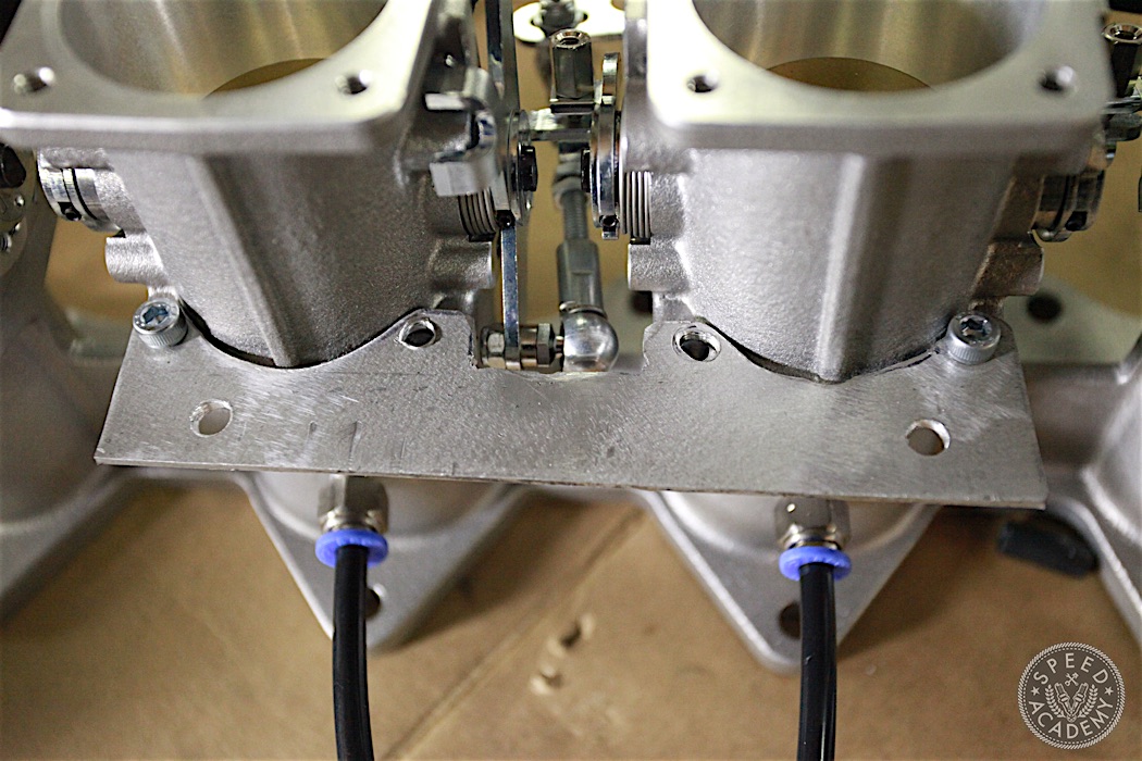
So where to mount the vacumm manifold? We decided to build this simple aluminum bracket for it to bolt to the underside of the Jenvey manifold using the existing bolts that attach the throttle bodies to the manifold. Once the velocity stacks and air filter are installed, the vacuum manifold and lines would be completely hidden, so we felt this was the best place for it.
If we decide to make a “Jenvey ITB Installation Kit” for S2000 owners, we’d use this same location for a bracket but have a prettier one laser cut for more of a precision look and fit. But given that the manifold completely conceals it, we’re really not to concerned about the prettiness of the bracket.
VACUUM SYSTEM PARTS LIST:
One (1) Vibrant Performance Part No. 2691 – Vacuum Manifold – Black Anodized; T6061 Billet Aluminum
Two (2) Vibrant Performance Part No. 11200 – Male NPT to Hose Barb Straight Adapter Fitting; NPT Size:1/8″; Hose Size: 1/4″
Eight (8) Vibrant Performance Part No: 2662 – Male Straight Fitting, for 1/4″ O.D. Tubing (1/8″ NPT Thread)
One (1) Vibrant Performance Part No: 11222 – Male NPT to Hose Barb Adapter, 45 Degree; NPT Size: 3/8″; Hose Size: 1/2²
One (1) Vibrant Performance Part No. 2104 – Vacuum Hose Bulk Pack, 1/8” (3.2mm) I.D. x 50ft – Black
I’m curious about the juxtaposition of all this _hard_ custom work for the ITBs, and keeping the A/C?
Wouldn’t the “easy” A/C delete (using the S2000 CR belt) drop a bunch more weight & simplify the engine bay?
(I wondered since I saw the a/c lines squeezed up against your FPR on the crossmember).
I’m looking to do an install on a different car, but was advised against pulling vacuum for the brake booster from the block since all the itbs are going there and that they only create vac, one at a time and the others bleed it away… but rather to tee from one of the itbs before it enters the box… Not sure what to do now..