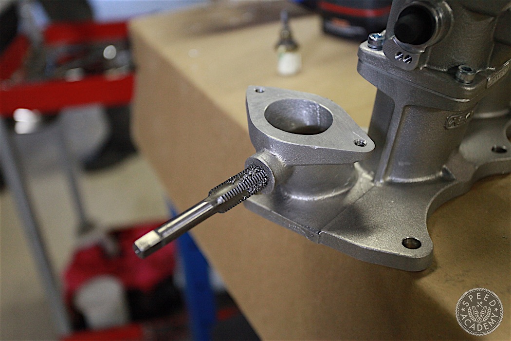
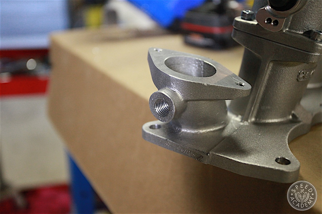
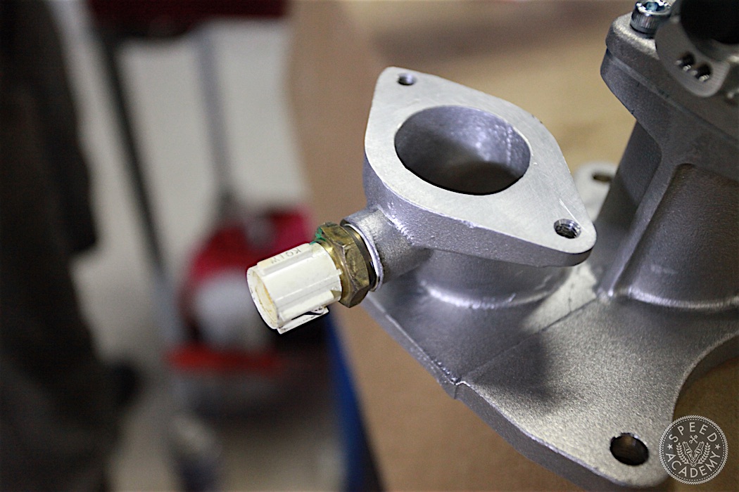
Now is as good a time as any to drill and tap the water neck for the thermostat housing for the OE water temperature sensor. Not a big deal. Just drill a hole and tap it for the size and thread pitch of the sensor. Again, Jenvey didn’t do this from the factory because they didn’t assume the kit was going to be used on S2000’s with factory wiring and sensors, but rather designed it for motorsport use where aftermarket sensors (including water temp) might be located elsewhere.
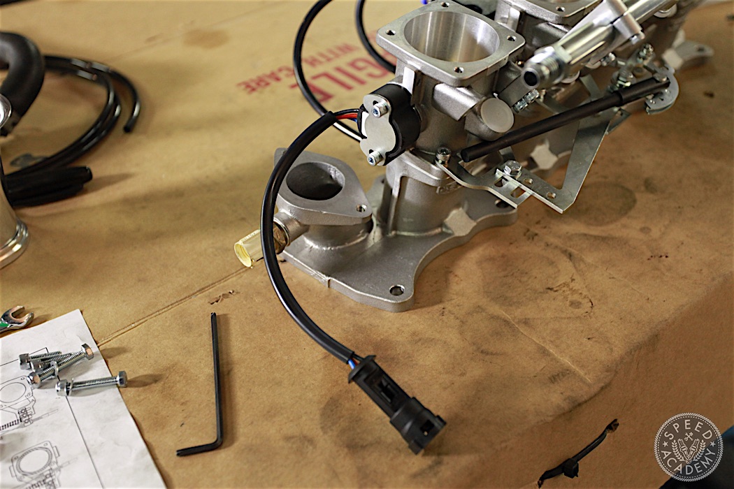
While we had the ITBs on the bench, we installed the throttle position sensor from Jenvey. This is a contactless hall effect TPS, and as you can see if comes with a motorsport grade econoseal connector.
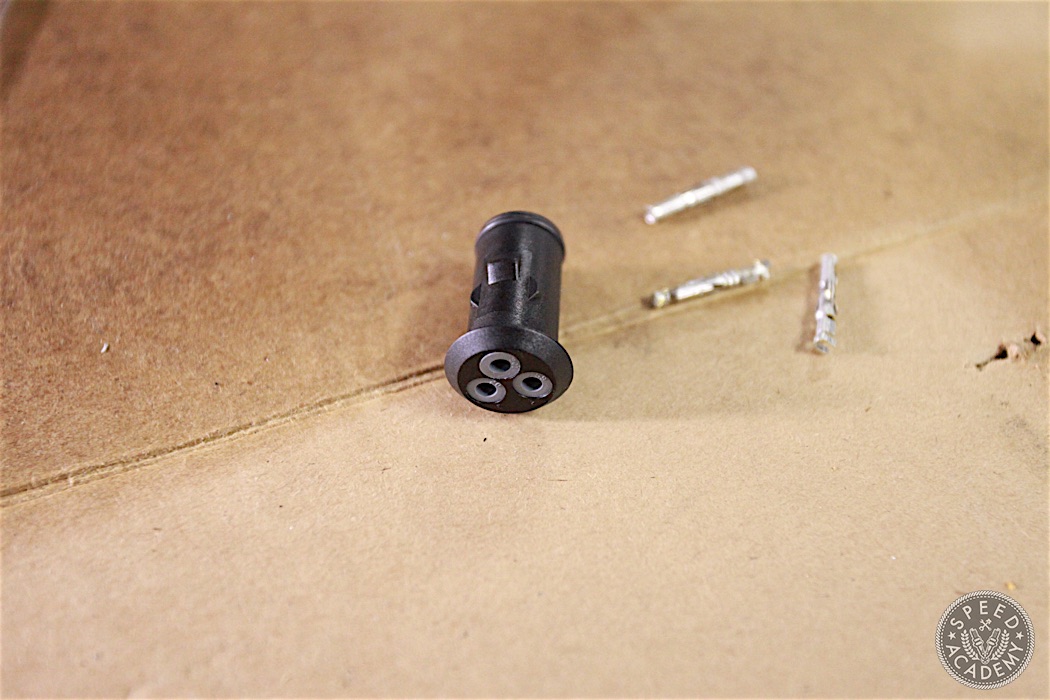
To connect the Jenvey TPS to the factory wiring harness, we cut the OE TPS sensor connector off the engine harness and crimped the three supplied pins onto the correct wires (we looked them up in the factory service manual) and plugged them into the provided econoseal plug.
Here’s the econoseal plug all wired up to the factory harness and ready to be plugged into the TPS connector.
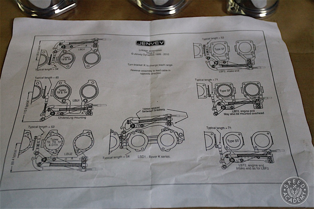
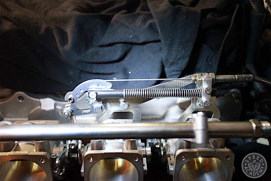
Before we could install the ITBs on the engine once and for all, we needed to install the throttle linkage assembly. As the above diagrams indicate, the linkage system can be installed on the topside or bottomside of the ITBs.
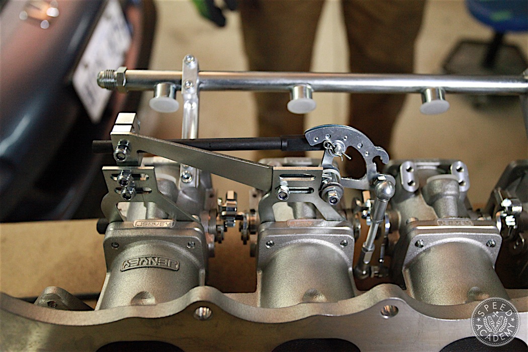
We began by assembling them on the bottomside for a tucked look, but quickly found that the rear linkage bracket doesn’t clear the S2000’s OE thermostat housing. So we abandoned the bottomside mounting and switched to the topside, where we had plenty of clearance and easy access for routing the throttle cable.
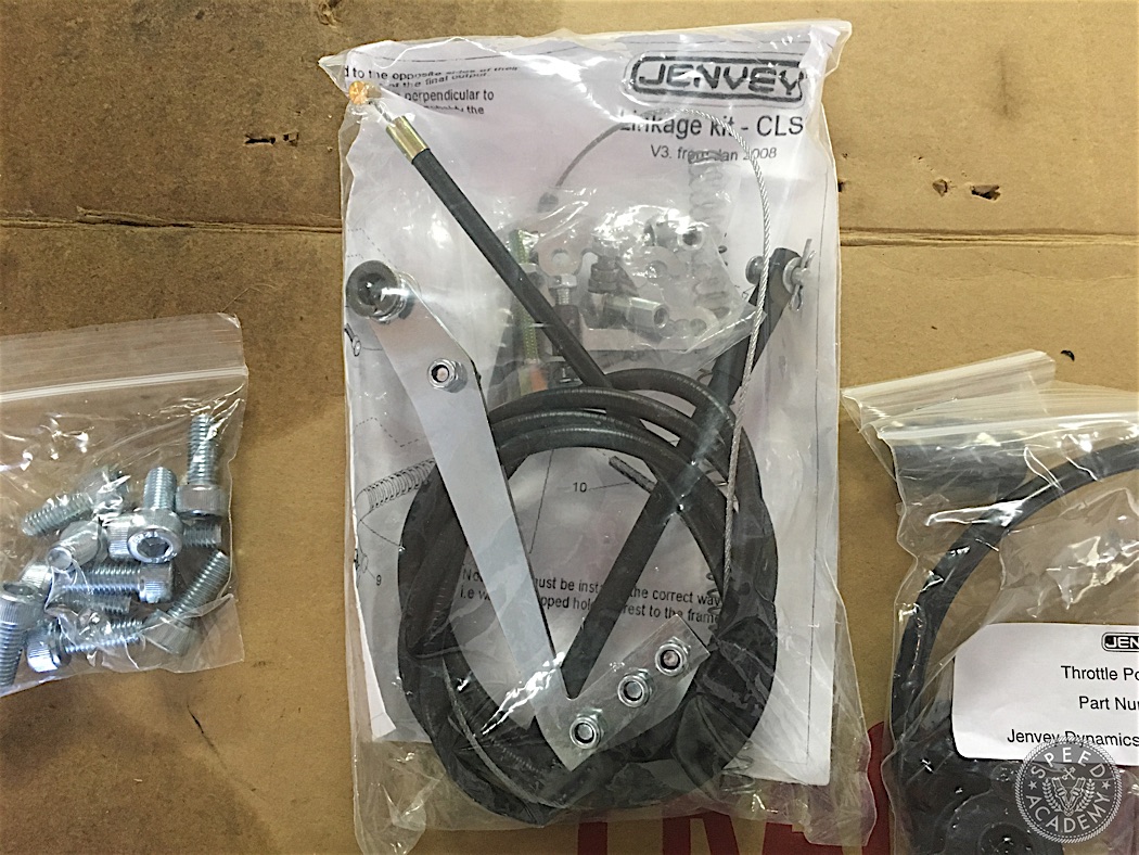
Figuring out how to mount the throttle cable and whether to use the OE cable or the Jenvey cable we bought with the kit took a bit of a think, but eventually we settled on the idea of using the OE cable and modifying the Jenvey cable mount bracket to suit it.
I don’t have any detailed photos of how we modified the Jenvey mounting bracket to work with the OE cable, but if you jump to the 8:43 mark of Part 3 of our video series on the installation you’ll see exactly how we did it. To summarize here, we drilled out the bracket and tapped the hole to accept the larger diameter and thread pitch of the OE cable. There isn’t a lot of extra material to work with on the bracket, but we’re confident the bracket (which is a small block of aluminum) is still plenty strong.
Although we didn’t use the Jenvey cable, within the Jenvey link kit that includes the cable, there’s a cable end that fastens to the cable via a pair of set screws. Because the OE cable was a bit too long, we cut the cable to length and then used the Jenvey cable end to attach it to the throttle cam. And just like that, we have a fully functional throttle cable setup!
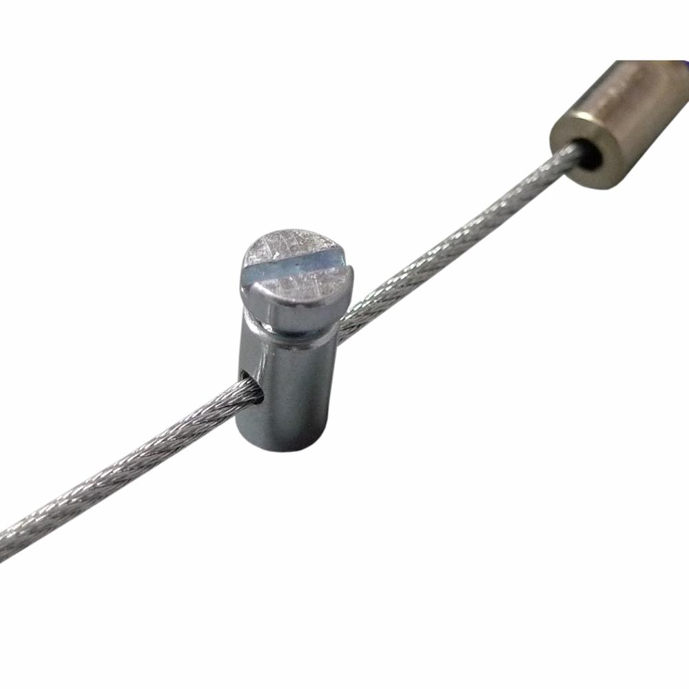
This isn’t the exact cable end that comes with the Jenvey kit, but it’s the same concept. The Jenvey one uses much smaller allen head set screws on each end that tuck away inside the cable end for a much cleaner appearance.

I’m curious about the juxtaposition of all this _hard_ custom work for the ITBs, and keeping the A/C?
Wouldn’t the “easy” A/C delete (using the S2000 CR belt) drop a bunch more weight & simplify the engine bay?
(I wondered since I saw the a/c lines squeezed up against your FPR on the crossmember).
I’m looking to do an install on a different car, but was advised against pulling vacuum for the brake booster from the block since all the itbs are going there and that they only create vac, one at a time and the others bleed it away… but rather to tee from one of the itbs before it enters the box… Not sure what to do now..